RV and Marine Battery Charging Basics

RV and marine batteries can be charged using many different kinds of charging systems, and understanding the way these chargers work can make a huge difference in whether or not you get the most out of them.

Not only are there differences between single stage charging and multi-stage charging, but in our experience, no two multi-stage chargers use the same charging algorithm. Also, the ability to program the settings on each charging system varies a lot from unit to unit.

Furthermore, some chargers, like converters, inverter/chargers and engine alternators, are powered by a consistent power source that allows them to operate at their maximum ratings at any time of day or night. Others, like Solar Charge Controllers and wind chargers are powered instead by an energy source that comes and goes.

In our eleven years of living off the grid in an eleven years of living off the gridlesstraveled.us/hitchhiker-2/” title=”2007 NuWa Hitchhiker 34.5 RLTG fifth wheel trailer RV” target=”_blank”>RV and a sailboat, we have relied on a wide variety of systems to charge our batteries. At times, we have used a converter, inverter/charger or engine alternator in conjunction with our solar charging system, and we’ve learned a lot about these systems and how to make them work together harmoniously.

The four parts in this series cover the following:

1. Battery Charging Basics – (this article) – Explains single-stage charging and multi-stage charging and explores the ways that certain products implement a multi-stage charging algorithm (no two are alike).

2. Converters, Inverter/Chargers and Engine Alternators – Discusses the differences between converters, inverter/chargers and engine alternators, which I lump together as “artificially powered” charging systems

3. Optimizing Solar Charge Controllers – Examines these “naturally powered” solar charging systems whose power source is the sun, which is very unreliable.

4. Combining Solar Power with Shore Power or an Engine Alternator – Reveals some of the subtleties of solar charging and gives some ideas for how to get the most out of a solar charge controller when it is run alongside a converter, inverter/charger or engine alternator.

This first post in the series has many sections, and you can easily navigate directly to them by using the links below.

WHY IS BATTERY CHARGING IMPORTANT for RVers and CRUISERS?

Return to top

Many people enjoy RVing and cruising without every relying on the house batteries for more than a few hours or an overnight. However, some of the joy of traveling with an RV or boat is being independent and free, and there is no better way to experience that freedom than to spend a few nights on your own, camped on public land or anchored in a quiet cove. Having well charged batteries makes a big difference in how comfortable you’ll be. Also, understanding the gear that charges your batteries can go a long way towards making sure your batteries perform optimally and are in the best condition possible.

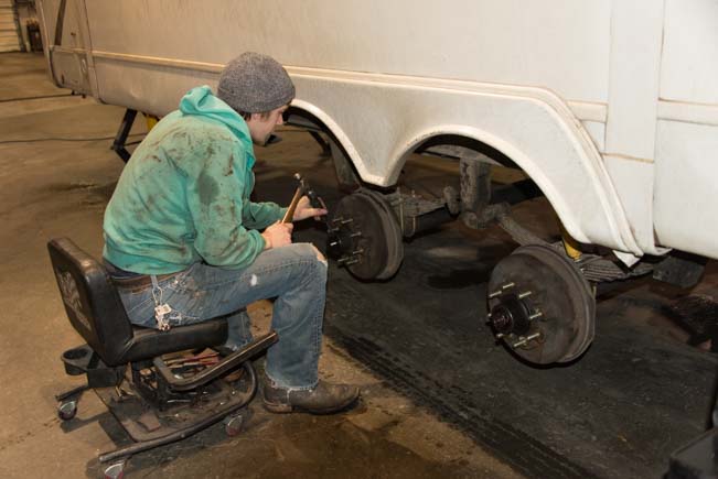
In our household, Mark is the one who does the installation work while I (Emily) am the one whose head is in the clouds somewhere thinking about theory and design. When Mark asks me to hand him a box end wrench while he’s peering into some dark corner of our boat or RV, I go rummaging around in all our boxes and stare at all the wrenches and wonder what he wants.

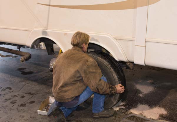
When the installation is finished, however, Mark washes up and washes his hands of all concerns about it. If he flips the switch and it runs, then he’s off the hook. “The factory settings are fine!” He tells me. “Set it and forget it!” But that’s the time when my curiosity just begins to get going. I want to know how it works, what makes it tick, and how it’s designed.

I admire Mark’s carefree and trusting attitude, and truly:

Your batteries will probably be fine if you click off this page right now and go read something more amusing.

But for those folks out there who just can’t pry their minds away from these things, I hope this four-part series will give you some food for thought. I make no claims to be an expert and am simply passing on the things I’ve observed and learned.


HOW BATTERIES ARE RATED

Return to top

In order to have a consistent standard for rating how much power a battery can store, manufacturers indicate how many amps of current draw it takes to drain their battery to 80% discharge (down to 1.75 volts per cell, or 10.5 volts for a 12 volt pattery) over a given time period. For “deep cycle” batteries this time period is 20 hours, and it is called the 20 hour amp-hour rating.

Batteries are also manufactured in standard sizes, including Group 24, Group 27, Group 31, 4D and 8D, for 12-volt deep cycle batteries, and GC2 for 6-volt batteries that power golf carts. The ratings are given in the manufacturer’s specs for the batteries and is often shown on a sticker on the battery itself.

These Amp-Hour ratings can range from about 70 amp-hours for a single 12-volt Group 24 battery to 220 amp-hours for a pair of 6-volt GC2 batteries to 230 amp-hours for a single 12-volt 8D battery.

Wait, what was that about a PAIR of 6-volt batteries??

When batteries are wired in series, the current draw remains the same while the voltage of the pair of batteries doubles. For this reason, when a 6-volt golf cart battery is rated with a 220 Amp-Hour capacity, wiring it to a second 6-volt battery to create a virtual 12-volt pair does not double its Amp-Hour capacity. Those two 6-volt batteries wired in series have the same old 220 Amp-Hour capacity that the single battery did.

The physical size of these battery types varies too, with a Group 24 12-volt battery weighing as little as 47 lbs and an 8D 12-volt battery weighing as much as 160 lbs. 6-volt golf cart batteries are the same width and depth as 12-volt Group 24 batteries, however they are a little taller and heavier, and they offer a lot more storage capacity per pair than a single 12-volt Group 24 battery does.

RVs are typically sold with Group 24 or Group 27 size batteries, either a single battery or two.

To beef up an RV’s battery bank, the easiest and most effective upgrade is to replace the single 12-volt battery with two 6-volt golf cart batteries wired in series. This will typically increase the battery capacity from about 70 amp-hours to 220 amp-hours.

An alternative upgrade option, if there isn’t enough height in the battery compartment for 6-volt batteries, is to add a second 12-volt Group 24 battery (if the first battery is new) or to replace the single 12-volt battery with two 12-volt batteries for an overall capacity of around 140 amp-hours.


HOW BATTERIES ARE CHARGED

Return to top

In essence, discharged batteries are a lot like hungry people. If you’re super hungry, you’ll dive into a big dinner with gusto. If you eat too much too fast, you’ll get sick! If you eat at a normal pace, you’ll slow down as the meal progresses, and eventually you’ll be full and you won’t want any more food.

Batteries are very similar. The food they want is current (amps), but if you feed them too much they get damaged!

Discharged (hungry) batteries can accept a lot of charge (current) at first. However, as they become more and more charged, they accept less and less current. A fully charged battery is around 12.7 volts. A fully discharged battery that still has enough life in it to be able to be fully charged again is around 11.6 volts. RV and marine house batteries will last longest if they are always kept above 12.0 volts, preferably above 12.1 volts.

The way a battery is charged is that some external charging device temporarily forces the battery to a higher voltage than its “fully charged” voltage of 12.7 by feeding it lots of current.

The fastest way to charge a battery is to put as much current into it as possible. As long as the charger is delivering lots of current, the battery’s voltage will rise. The charger itself must be at a higher voltage than the batteries to do this. If the charger is around 13.5 volts, it can force a modest amount of current into the batteries. If it is around 14.5 volts, it can force in a lot more current.

During charging, the battery voltage will rise into the high 12 volt range, then it will move into the 13 volt range, then 14, and so on. It takes time for the battery’s voltage to rise as it is fed current. A more deeply discharged battery will take longer to reach a given voltage than a minimally discharged battery will.

If the charger is turned off so no current is going into the battery, the battery will gradually fall back to is own “internal” voltage. This may take 15 minutes or more. If it has been charged for a while, this voltage will be near or at the “fully charged” value of 12.7 volts. If it hasn’t been charged long enough, the battery’s internal voltage will be lower than that.

For instance, if a battery is partially discharged to 12.4 volts, the way to get it charged back to 12.7 volts is for a charging system to give it a bunch of current and temporarily force it up to some higher voltage in the 13 to 15 volt range. The charging system itself will need to be at a higher voltage than whatever voltage it is trying to get the battery to.

After a while, when the charging system is turned off and the battery is allowed to settle back down to its own internal voltage, it may drop back to 12.7 volts, in which case the battery is fully charged. However, the battery may settle back down a little lower — perhaps to 12.5 volts — which means it could use a little more charging to reach a fully charged state.

BATTERY CHARGE STATES

Return to top

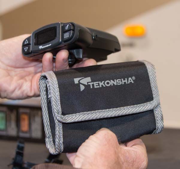
The following chart shows the different voltages batteries have when they are charged or discharged. If you have nothing running in the rig (no computers running, no TV, no vacuum or toaster, etc.), you can measure the battery voltage using a hand-held voltmeter in DC volts mode by placing the two probes on the two battery terminals. This is what we do. You can also install a simple volt meter on the wall of your coach or install a fancier battery monitor.

Battery charge state chart

Data from Trojan Battery, rounded to tenths for easy memorizing.
Note that the values decrease by 0.1 volt for each 10% drop until 60%.

If the battery has just finished charged for a few hours, there will be a surface charge on the metal plates inside of it which will raise the voltage by a tenth of a volt or so. Running an appliance for a few minutes in the RV or boat will remove that surface charge so you can see the battery’s true internal voltage.

On the other hand, if a lot of appliances are running in the rig, current will be being drawn out of the battery and the battery’s voltage will be lower than its true internal voltage. Turning everything off and waiting a few minutes will bring the battery back to its true internal voltage.

UNDERCHARGING, OVERCHARGING and EQUALIZING

Return to top

Batteries are filled with thin metal plates and battery acid (electrolyte). As a battery’s voltage is raised, the internal chemical reactions inside the battery make the electrolyte heat up. If the voltage is raised high enough for long enough, the acid begins to release gases (like hot water beginning to steam), and eventually the acid begins to boil.

Trojan Reliant 12 volt AGM battery metal plates inside

Looking down into the battery cells of four 12 volt Trojan flooded batteries
before the electrolyte is poured in.

Raising a 12 volt battery to a voltage in the high 14’s or more for a few hours is enough to make the batteries begin to start gassing. Reducing the voltage to the mid-13 volt range stops the gassing.

Some trickle chargers don’t allow the battery voltage to rise above the mid-13 volt range to avoid having the batteries begin gassing. However, the less a battery’s voltage is raised, the less current will go into it and the less the battery will be charged after a given number of hours. It is possible for the battery to become fully charged at a lower voltage, but it will take much longer.

The engineers at Trojan Battery have told us that almost all the dead batteries they have studied over the years have been chronically undercharged. Overcharging is a much less common problem.

When batteries are chronically undercharged, they develop lead sulfate crystals on the lead plates inside the battery. This is called sulfation. This material reduces the battery’s capacity, and it can even form a bridge from plate to plate, creating an internal short and rendering the battery useless.

With flooded (wet cell) batteries, raising the battery voltage very high (15 volts or more) for a few hours heats up the electrolyte until it gasses and boils and sloughs the sulfate material off the metal plates. The material then settles on the bottom of the battery underneath the plates where it doesn’t risk forming a bridge between the plates. This process is called Equalizing.

Equalizing is done only on wet cell (flooded) batteries. Gel and AGM batteries are sealed and cannot release gasses, so they can actually be damaged by charging them at a very high voltage in this manner.

There is no definitive moment when a battery is fully charged. It is similar to feeling full at the end of a meal. After a great dinner, you can usually find room for a yummy sliver of pie, or maybe just one bite of your spouse’s pie, but you can definitely leave the table feeling full without having any pie at all. RV and marine batteries are much the same in that they can usually accept another fraction of an amp of current from a charger even though they are essentially full charged.


LEAVING A BATTERY DORMANT – “LOT ROT”

Return to top

Batteries need to be used, and the worst thing that can happen to a battery is that it doesn’t go through regular discharging and charging cycles. Like a person who needs to exercise to to burn calories and give them a good appetite so they can consume some nutrition, batteries need to be used (discharged) and then charged up again to maintain peak health.

RVs and boats that are stored without being plugged in to shore power for long periods of time will slowly have their batteries discharge completely over a period of months. That’s not good! There’s nothing like coming back to the RV or boat to find dead batteries. However, if the RV or boat is left plugged into shore power to avoid this problem, even though the batteries will be fully charged at the end of a few months, they may still die a premature death due to not getting enough exercise and not being used.

For RVs and boats left on a charger for months at a time, whether or not the owners are living on board, a charger that periodically raises the battery voltage above a trickle charge will help prolong the battery life. Occasionally unplugging from shore power and running some appliances for a few hours will give them a good workout too.

The engineers at Trojan Battery have spent years studying car batteries that have died. The most common failure they find is what they call “Lot Rot” caused by cars that are used infrequently and drive only short distances.

SIZING A CHARGER to a BATTERY BANK

Return to top

Battery chargers come in all sizes with maximum current output ratings that range from a few amps to hundreds of amps. One rule of thumb for sizing a battery charger to a battery bank is for its maximum current output rating to be roughly 25% of the amp-hour capacity of the battery bank.

RVers and sailors that plan to boondock or anchor out a lot tend to replace the factory installed battery banks with bigger ones. In this case, it is worthwhile to review the sizes of the factory installed charging systems to make sure they will be big enough to charge the new battery bank efficiently.

For instance, an RV or boat shipped with two Group 24 12 volt batteries that have a combined amp-hour capacity of 140 amps wil be fine with its factory installed 55 amp charging system. But if those batteries are upgraded to four 6 volt golf cart batteries with a combined capacity of 450 amp-hours, a larger charging system will perform better.

SINGLE STAGE CHARGING

Return to top

A single stage charger will deliver enough charge to keep the batteries at a set charging voltage indefinitely. At first, the batteries will require a fair amount of current to be able to maintain that voltage. But as time goes on they will need less and less current to maintain that voltage. If the charging system is turned off, they will drop down to their own “internal” voltage. If that internal voltage is 12.7 volts, then they are fully charged. If not, they need to be put back on the charger!

This kind of single stage charging system works okay, but it is inefficient and risks undercharging or overcharging the batteries.

Automotive battery chargers generally charge the batteries at a high voltage (in the mid-14 volt range). This is fine for a while, but the batteries can’t be left on this kind of charger for very long or they will overcharge. An alternative is a single stage trickle charger that charges the batteries at a modest voltage (in the mid-13 volt range). This is how a lot of cheaper RV battery chargers (converters) work.

The problem with a single stage trickle charger is that it takes a very long time for the batteries to reach full charge. That’s okay if you are plugged into shore power for a few days, but if you are running from a generator, do you really want to run it for 12 hours just to get the batteries charged?

Also, a single stage charger never pushes the batteries up to a higher voltage, something that is considered helpful for prolonging battery life.


MULTI-STAGE CHARGING

Return to top

A more efficient charging system is to give the batteries a lot of current at first, while they are most depleted, and then to back off, forcing less current into them once they are fairly well charged up. This is what multi-stage charging systems do.

Multi-stage chargers generally have three stages: Bulk, Absorb and Float.

Bulk Stage

In the Bulk stage, the battery is given as much current as the charging system can deliver. As the batteries accept this charging current, their voltage slowly rises. Eventually the batteries reach the “Bulk Voltage” which is something in the range of 14.3 to 14.8 volts, depending on the charger, the battery manufacturer’s recommendations and/or your own personal choice.

Absorb Stage

At this point the multi-stage charger switches tactics. Rather than giving the batteries as much current as the charger can deliver, the charger instead gives them only as much current as it takes to keep them at a particular voltage known as the “Absorb Voltage” (which is also usually between 14.3 and 14.8 volts). While the batteries are held at the Absorb voltage, they are in the Absorb stage (this is called the “Accept” stage by some manufacturers, but is more commonly known as the Absorb or Absorption stage).

The idea in the Absorb stage is that rather than force feeding the batteries all the current the charging device can deliver, the batteries are given just enough to keep them at the Absorb voltage. At first, this is pretty much the same amount of current they were getting in the Bulk stage. But after a while, the batteries don’t need as much current to be able to maintain the Absorb voltage. So, over time during the Absorb stage, the multi-stage charger delivers less and less current to the batteries, and the batteries just “hang out” at the Absorb voltage, getting force-fed a steadily decreasing amount of current.

Float Stage

At the end of the Absorb stage (and what defines “the end” of the Absorb stage is one of the areas where manufacturers and devices differ the most), the multi-stage charging system switches tactics again. Now, rather than holding the batteries at the relatively high Absorb voltage of 14.3 to 14.8 volts, the charger will hold the batteries at a much lower Float voltage in the range of 13.3 to 13.6 volts.

Of course, the batteries will require a lot less current to maintain this lower voltage, so the charger will now be delivering a much lower current. And again, as time progresses, the amount of current that the batteries need to maintain the Float voltage will diminish. At first, the batteries will need a fair bit of current to maintain the Float voltage, but as the hours go by they will require less and less. As with the Absorb stage, the batteries will just “hang out” at the Float voltage during the entire Float stage.

When the batteries reach the Float stage they are considered to be pretty nearly fully charged. If the charger is turned off at this point, the batteries will eventually settle down (after a few minutes) to their own internal voltage, and that voltage will be around 12.7 volts, indicating that they are fully charged.


PREMATURELY TURNING OFF A MULTI-STAGE CHARGER

Return to top

Of course, the multi-stage charger could be turned off at any time during the charging process, before the batteries are fully charged. Why? Well, during Bulk or Absorb or Float you might unplug the shore power cord so the RV or boat can go somewhere, or you might turn off the generator for quiet hours in the campground, or the sun might set, making the solar panels ineffective, or an engine with a built-in engine alternator might be turned off when the sails are raised on a sailboat or the motorhome is parked, etc.

These are all arbitrary events that could happen at any point in the multi-stage charging process.

When this happens, the batteries are more charged than they were, but they aren’t necessarily fully charged. In other words, if the multi-stage charger is turned off before the batteries are fully charged, the batteries will gradually settle down to their own internal voltage, whatever it is at that point. It might be 12.4 volts or 12.6 volts — who knows! Obviously, it should be a higher voltage than when the multi-stage charger first started charging the batteries.

For most mutli-stage chargers, when they resume charging the batteries, they begin the process all over again, first going through the Bulk stage, and then the Absorb stage, and then the Float stage. But again, different manufacturers and different products handle this scenario various ways.

EQUALIZING – A FOURTH CHARGING STAGE

Return to top

Most multi-stage chargers have a fourth charging stage which is intended to help wet cell (flooded) batteries last longer. This stage is not needed or used by Gel or AGM batteries. In the “equalize” stage, the charger raises the batteries to an even higher voltage than the Bulk or Absorb voltage for a few hours (generally in the mid-15 volt to low 16 volt range). During this time the battery acid (electrolyte) inside the battery will heat up and begin to boil, sloughing the sulfation off the metal plates in the battery and letting it drop down to the bottom of the battery underneath the plates.

Outback MX60 Solar Charge Controller in Equalization Stage

Here, our Outback solar charge controller has held the batteries at 15.8 volts for 47 minutes during an Equalize stage. At this moment it required 17.4 amps to keep the batteries at 15.8 volts.


LEAVING A MULTI-STAGE CHARGER ON INDEFINITELY – MANAGING THE FLOAT STAGE

Return to top

Converters and inverter/chargers on RVs and boats that are plugged into shore power all the time charge the batteries 24/7 and never stop. The way that multi-stage chargers manage their Float stage is one of the big differences between them.

Some chargers keep the batteries at a Float voltage all the time, forever, until they are turned off. Some periodically “reboot” automatically and go back through the Bulk and Absorb stages. A few provide you with a way to force the charger back into the Bulk stage to start the charging process over again manually if you need to.

Periodically leaving the Float stage and going into Bulk and Absorb will help prolong the battery ilfe.


WAIT – WHAT’S THE DIFFERENCE BETWEEN BULK and ABSORB AGAIN?

Return to top

Generally, the Bulk voltage and the Absorb voltage are the same value, or very close, so the only difference between the Bulk stage and the Absorb stage is how much current the batteries are receiving.

In Bulk, the charger is delivering its maximum amount of current to the batteries to raise them up to the Bulk voltage. A small charger’s maximum current will be less than a large charger’s maximum current is, so a small charger will get the battery up to the Bulk voltage more slowly than a big one will. Either way, the chargers are working at their peak in the Bulk stage, pouring as much current into the batteries as possible.

In Absorb, the goal is to keep the batteries fixed at the Absorb voltage, so the batteries are given only enough current to keep them there. The amount of current they need to do this drops off over time.

So, in the first case the batteries are ramping up to the Bulk voltage due to receiving as much current as the charger can deliver, while in the second case the current going to the batteries is steadily decreasing because they are being given only enough current to keep them at the Absorb voltage.

CONCLUSION

These are the basic concepts involved in charging RV and marine battery banks. I’ve mentioned a few times how manufacturers and charging systems vary, and in the following posts I will be showing what those variations are.

To continue to the next article in this series, click here:

RV Converters, Inverters and Engine Alternators

Here are links to the each article in this four part series:

Subscribe
Never miss a post — it’s free!

For more info:

Related posts about batteries, solar power and living off the grid in an RV or boat:

Our most recent posts:

More of our Latest Posts are in the MENU.   New to this site? Visit RVers Start Here to find where we keep all the good stuff. Also check out our COOL NEW GEAR STORE!! *** CLICK HERE *** to see it!

Solar Tutorial Part IV – Solar Panel Selection and Wiring

<- Solar Tutorial Part III – Full-timer Kits                                                         Solar Tutorial Part V – Battery & Inverter Selection ->

The two sample systems described in Part III of our Solar Power Tutorial series are essentially the same systems we have installed on our RV and sailboat.  The RV system is pretty standard for full-time RVers (four 120-140 watt 12-volt panels and 440 amp-hour battery bank).  The sailboat system is bigger than many cruisers carry (three 185 watt 24-volt panels and 710 amp-hour battery bank).

Cruisers often install less solar power and rely on additional charging methods via engine alternator, and wind/gas/diesel generators.  However, we have found our solar power alone is sufficient to live an ordinary house-like lifestyle on our boat (if we don’t use our standalone DC freezer).  We lived for 10 mid-winter weeks in southern Mexico on solar power alone, without using the alternator once (it was broken), and still used two laptops, the TV/DVD, stereo, microwave, chartplotter, autopilot, anchor windlass and vacuum as much as we wanted.

Our rationale for having enough solar power to live comfortably without alternative charging methods was:  we didn’t want to store a lot of gasoline to power a gas generator; we had found that boats with wind generators often suffered from the whirring noise and vibration; and we didn’t want the added cost, installation work and maintenance of an inboard diesel generator.  Solar power has been a great solution for us on both the boat and the fifth wheel.

Part III described these two basic full-timer systems with just a cursory comparison of the solar panel choices.  This page goes into more detail about the various options for sizing solar panels and suggests different ways to wire them.

Wiring in Series versus in Parallel and Wire Gauge Size

There are quite a few choices for solar panel configurations, each with its own pros and cons.  But before choosing a panel configuration it’s worthwhile to consider how to deal with the large current that will be flowing through the wires.  As much as 35 amps or more might be flowing from the panels to the charge controller and then from the charge controller into the batteries.  This requires heavier gauge wire which is more difficult to work with and is expensive.  However, there are several ways to reduce the amount of current in the wires.

If the panels are wired in parallel, the amps produced by each panel are additive while the volts remain constant (Ohm’s law).  Therefore, the cable leading from the connection point of all the panels to the charge controller and then on to the batteries will carry the full current load, or potentially as much as 35 or 40 amps at 12 volts DC.  Heavier gauge wire must be installed to handle this large current load throughout the system.

If there is too much current on a cable, then it will get warm (or hot), and lose some of its precious amperage to heat.  In other words, if the wire gauge is too small, not all the power produced by the panels will make it to the batteries.  It will dissipate as heat loss along the way.  And at the extreme, there’s the risk of melting the shielding off the cable (highly unlikely).

Larger wire is more expensive and is more difficult to handle because it is stiffer.  “Larger” generally means 6 or 8 gauge wire and “smaller” is generally 10 gauge.  The size is dependent on the current flowing through the wire and the length of the wiring run.  A detailed chart for selecting wire gauge is given here.  Note that some charge controllers can’t accommodate wire heavier than 4 or 6 gauge.

If the panels are wired in series, the amps produced by each panel stay constant while the voltage is additive (also Ohm’s law).  Therefore, the cable leading from the connection point of the panels to the charge controller will carry just the amperage produced by a single panel (7-9 amps) at 48 volts DC (if four 12 volt panels are installed in series), rather than the 25-35 amps at 12 volts DC that would flow when wired in parallel.  Because there is less current, thinner gauge wire can be used throughout the system.

In practical terms, most solar power systems on RVs and boats never reach their full potential current load.  During the morning hours, before the sun gets high and powerful in the sky, the batteries get quite a bit of charge.  Usually, by the time the sun is really cranking out maximum energy at noon — the time when the system could be producing max amps — the batteries have already gotten pretty well charged and are starting to ask for less and less current.  So the charge controller has already begun to throttle the panels back a bit and less current is flowing through the system.

Also, solar panels are rated for operating with the sun perpendicular to their surface, and anything other than a perpendicular orientation reduces their output significantly.  In all months except May-July, the sun doesn’t ride all that high in the sky.  We have rarely seen much more than 25-30 amps on either of our full-timer systems, although they are capable of 30 and 36 amps respectively.

Another important consideration is that when a small fraction of a solar panel is shaded — as little as a 4 square inch area on a 2′ x 5′ panel — the entire panel stops producing power.  That is because internally the panel is “wired” in series.  When there is resistance, caused by shade, in just one portion of it the panel’s internal circuitry, current can’t flow through any of it.

By extension, if the panels are all wired in series, when one panel shuts down due to a palm-sized bit of shade, then the entire array of panels shuts down.  A tree branch or part of a boat’s standing rigging or mast/boom can cause the entire array to shut down if it is wired in series.

marine solar panels on hunter 44ds sailboat

Shade from the mast and shrouds on our three 185 watt panels.

If the panels are all wired in parallel, a small amount of shade on one panel will only shut down that individual panel.  Current will still flow through the rest of the panels and then through the rest of the system.

We were persuaded by our solar panel vendor to wire our trailer’s panels in series so we could use small gauge wire throughout the system.  We have experimented with shading a small corner of one of the four panels and were stunned to see the entire array quit working!  However, almost everywhere we boondock we are in full sun.  So, in the end, it doesn’t matter for us. Wiring our RV’s solar panels in series has worked out just fine.   If, however, you anticipate camping under trees on a regular basis and you want to maximize the panels’ chances of getting access to the sun, wire the panels in parallel and use heavier gauge wire.

On a boat, this series versus parallel decision is much more critical than on the roof of an RV.  The mast, boom and shrouds often shade portions of the panels as the boat swings at anchor.  Under sail the shading can be even worse.  So the best wiring option on a boat is to wire the panels in parallel.  However, the cable runs in a boat can be much longer than in a comparably sized RV.  On our sailboat the wiring running from one end of the system to the other — panels-controller-batteries — is 45′.  Why so long?  The panels are high in the air on an arch at the back end of the boat, the batteries are at the bottom of the hull in the middle of the boat, and the all the wiring is routed so as not to be seen.

12 volt versus 24 volt panels

Another way to tackle this issue of having a lot of current flowing through the system is to use 24 volt solar panels instead of 12 volt panels.  When the voltage is doubled like this (24 versus 12 volts), the current is halved.  So the current produced by 24 volt panels is half that of equivalent wattage 12 volt panels (the watts don’t change whether the panels are 12 volts or 24 volts).  We chose to go this route on our sailboat, using three 185 watt 24 volt panels wired in parallel.

Since the batteries are 12 volt batteries, the input side of the charge controller coming from the solar panels is 24 volts while the output side going to the batteries is 12 volts.  Most large capacity charge controllers allow this kind of configuration.  This means that the current flowing between the panels and the charge controller is half that flowing between the charge controller and the batteries.  So, while the panels may be producing 14 amps at 24 volts, and those 14 amps may be flowing from the panels to the charge controller, the current will double to 28 amps at 12 volts when it flows from the charge controller to the battieries.

While the wiring run between the panels and the charge controller can be smaller gauge (less current flows in that portion of the system), the last wire run between the charge controller and the batteries needs to be as short as possible and wired with heavier gauge wire to accommodate the larger amount of current.

We made the mistake of placing the charge controller 25′ from the batteries at first and using 10 gauge wire (I suspect we didn’t explain our situation to the salesmen at the solar panel store well enough when we asked him for guidelines).  When the panels were running at full power we lost about 10-15% of the power they were producing.  Once we moved the charge controller to within 10′ of the batteries and replaced the 10 gauge wire with 8 gauge wire, we lost just 1.5% of the power between the charge controller and the batteries, which is considered acceptable.

Tilting Brackets

Tilting brackets make a lot of sense on an RV because an RV is parked in a stationary position.  In wintertime it is possible to tilt the panels towards the sun (tilt them about 45 degrees).  Most folks align the panels with the length of the RV and tilt them on their sides.  This means that either the driver side or passenger side of the RV will be situated to face due south and the panels will be tilted in that direction.  In most boondocking locations we find we can orient the rig any way we want to because there is so much space around us.

In experiments one December with RVing neighbors who had tilting brackets, we found that their solar power system produced about 40% more amp-hours throughout the day.  Their system was fully charged and their batteries were floating in the afternoon, while ours never reached the Float stage.  Some of that may have had to do with their batteries being better charged to begin with in the morning (we have no idea if they were or weren’t), but it is a pretty dramatic difference nonetheless.

RV solar panels on fifth wheel trailer

Four 120-130 watt panels on our fifth wheel’s roof

However, to get the advantage of tilting brackets, you have to get on the roof to tilt each panel every time you set up camp, and then remember to return them to their flat position before breaking camp and driving off. 

An alternative is to keep the panels flat in all but the most dire circumstances (a week of cloudy winter days), but have one more panel in your system than necessary.  Or don’t even bother installing tilting brackets at all. The trade-off is a few hundred dollars for an extra panel versus climbing up and down your RV ladder and fussing with the panels, as well as the risk that you might drive off with them raised up (we’ve seen plenty of people do that).

Tilting brackets don’t make much sense on a boat because boats move around so much at anchor.  Ours swings back and forth in a 90 degree arc.  Also, the tilting mechanism for a lot of boats introduces shade across the panels at certain angles.  On a boat, it is best to mount the panels as far from the mast and boom as possible and to focus on keeping the shade off the panels as much as possible by forcing the boom off to one side or the other while at anchor.  A fixed, flat mounting position works best.

 For more information about how to select the best solar panels for your installations, see this article:

Which Solar Panels To Buy – Flexible or Rigid? 12 or 24 volt? Monocrystalline or Polycrystalline?


Most of the components for an RV or marine solar power installation can be purchased at Amazon.

Shown here is a complete full-timer's kit (far left), a big charge controller (middle) and a big inverter (right). More comprehensive listings of each component type can be found at the following links:

Purchases at any of our Amazon links help cover our out-of-pocket costs for operating this site -- thanks!


This is the end of our solar power tutorial series.
We have lots of other info about solar power on this website. See the pages listed below to learn more.

Subscribe
Never miss a post — it’s free!

FURTHER READING and RELATED ARTICLES

SOLAR POWER OVERVIEW and TUTORIAL

BATTERIES and BATTERY CHARGING SYSTEMS

LIVING ON 12 VOLTS


Our most recent posts:

More of our Latest Posts are in the MENU.   New to this site? Visit RVers Start Here to find where we keep all the good stuff. Also check out our COOL NEW GEAR STORE!! *** CLICK HERE *** to see it!

Solar Tutorial Part III – Full-time RV & Cruising Solar Systems

<– Solar Tutorial Part II – Starter Kit
Solar Tutorial Part IV – Panels & Wiring –>

This page outlines the parts needed for two different solar power systems to be used for full-time “off the grid” living in a moveable home: one for an RV and one for a sailboat

If you are going to live in your RV full-time, year-round, you will need a much bigger system than the one described on the previous page.  You will likely be using your computer a lot, you’ll keep the lights on for many evening hours in the winter, you’ll be using the TV and stereo quite a bit, and you will want to use your microwave, hair dryer, vacuum and toaster on a regular basis. 

Compared to the small-medium sized systems described in our Solar Power Tutorial Part II, this will require more total wattage in the solar panels, a bigger and more sophisticated charge controller, more total amp-hours in the batteries and a better quality inverter that is wired into the RV’s AC wiring system.  At the very least, a full-timer’s system should have 400 watts of solar panels, a 40 amp charge controller, 400 amp-hours of battery capacity and a 1000 watt inverter.

Full-time RVers Solar Power System – 12 Volt

A sample full-time RVer’s solar power system consists of the following:

4 150 watt (12 volt) solar panels ($900)
1 Outback FlexMax FM60 MPPT charge controller ($550)
10 gauge wire rated for outdoor use (or 8 guage) ($100)
4 6-volt golf-cart style batteries ($1,050)
1 Go Power 2000 watt pure sine wave inverter ($850)

Total parts cost:  ~$4,000

Wild guess at an installer’s fee:  ~$1,500

* Additional parts may include MC4 connectors and transfer switch and Cable and DC circuit breaker for the inverter

Full-time RV solar panel installation

The 12-volt 120- to 130-watt panels are sized about right to fit between the many little things that stick up on our fifth wheel’s roof.

This system is rated to produce 600 watts at 12 volts and has a 440 amp-hour battery bank.  It is a little bit larger than the system that we have on our fifth wheel trailer. Ae have three 120 watt panels and one 130 watt panel (for a total of 490 watts), and our system cost a whole lot more back in 2008!

We can get as much as 170 amp-hours per day in summer, although more typically it is about 120 amp-hours.  There have been summer days/nights when we watched our 26″ TV for 15 hours (the Olympics), and there have been days/nights when we ran two laptops for 10 hours and then watched a movie (such couch potatoes!!).

In the dead of winter, around the winter Solstice (December 21), this system can produce about 80-100 amp-hours per day.  The only limitation in winter is when storms cloud the skies for three or more consecutive days.  Three cloudy winter days in a row where we get just 40-60 amp-hours makes us start thinking about supplemental charging or cutting back on our power use.

Our weird choices for solar panel sizes were due to what we already owned from our first solar panel installation (a 130 watt panel) and what was available in the store at the time of purchase (120 watt panels).  If we were buying today, we would have purchased four 150 watt panels as shown above.

This system will allow you to run everything inside your rig but the air conditioner and big power tools.  We have even used it to run a small compressor to change a flat tire on the rig (on four different occasions, ugh!).


RV Full-timer’s System Installation

Installation follows the same guidelines as the smaller systems described in our Solar Power Tutorial Part II, but is just a little more complicated.  An outline of the installation follows.

(1) Install the solar panels on the roof

We wired ours in series, but wiring in parallel may be preferable.  A discussion about the pros and cons of wiring the panels in parallel versus series comes on the next page of this tutorial along with a discussion of wire gauge sizes.  Run the wires down through the refrigerator vent to the battery compartment. If the fridge is in a slide-out, run the wires down the outside of the gray or black water vent pipe

(2) Install the batteries in the battery compartment

Not many RV’s have enough battery boxes for four 6-volt batteries, especially trailers.  Often the battery boxes are too short as well, since 6-volt batteries have the same footprint but are taller than the typical 12-volt Group 24 batteries that are shipped with RVs from the factory.  Here are example 6 volt battery boxes and Group 24 12 volt battery boxes.

If you haven’t purchased your RV yet, you may be able to get the manufacturer or dealer to modify the battery boxes for you as part of the deal (that’s what we did with NuWa on our fifth wheel).  Wire two pairs of the batteries in series to form two 12-volt batteries, and wire those two pairs in parallel.

RV Solar Panel Installation Outback Charge Controller

Outback 60 amp charge controller

(3) Install the solar charge controller near the battery compartment

Connect the wires that come from the solar panels to one side of the charge controller and wire the batteries to the other side.  It is best to crimp eyes on the ends of the cables.

(4) Install the inverter near the battery compartment

Wiring the inverter to the AC wiring system in the RV is complex.  The proper way to wire it is to place the inverter as close to the batteries as possible. Protect the DC side with a big fuse, and wire it to a transfer switch. We are not master electricians, and we took a short cut on our system that not everyone would be comfortable with but that works very well for us.

We positioned the inverter next to the DC to AC converter in the basement of the fifth wheel and wired it directly to the batteries.  The converter is located next to an AC outlet that it uses for power to run (the converter uses the AC power to charge the batteries). 

When we use shore power, we plug the converter into the AC outlet to allow the converter to do its normal job of charging the batteries.  However, we use shore power only a few nights a year, at most.

When we dry camp, which we do virtually 100% of the time, we unplug the converter from the AC outlet so it is totally dormant and not in use, and then we plug the inverter into the AC outlet instead.

The inverter and converter are never “on” at the same time.

The inverter draws its power from the batteries and converts that DC power into AC power. That is, it generates AC power which it supplies to the rig backwards through the AC outlet it is plugged into.

This is very non-standard and would be frowned upon by master electricians.  What would concern them is that when the rig is in this configuration, the shore power outlet on the outside of the trailer is live, with power coming out. Accidentally plugging the shore power cable into the shore power outlet on the outside of the RV while the inverter is turned on would be disastrous. However, because we almost never use our shore power cable and we rarely change our setup to switch between dry camping and hooking up (since we dry camp almost exclusively), this method has worked fine for us for over seven years.

This is not a recommended strategy if you plan to switch between dry camping and using electrical hookups frequently.

We also connect the two 50 amp AC legs of our 50 amp coach by plugging a modified extension cord with a male connector on each end into one outlet on each leg. We have two outlets next to each other in the bedroom, one on each of the 50 amp legs in the trailer, that are ideal for this purpose. We plug the “cheater” cord into each outlet, effectively connecting the two 50 amp halves of the RV together at that point.

It is handy to wire the inverter to a simple toggle switch located somewhere inside the RV so you can turn the inverter on and off from inside the rig without having to go outside to the battery compartment each time you want to turn on your AC power.

Liveaboard Cruiser’s Solar Power System – 24 Volt Solar Panels

Marine sailboat solar panel installation

A large arch installed off the back end makes it possible to use very big panels. Note the shade on the panels from the mast and shrouds. The panels are producing about 50% of their potential power right now!

A system like the above would work fine on a sailboat.  However, another style of design — which we ended up using — is the following.  Of course, this system could be used on an RV as well.

3 250 watt (24-volt) solar panels ($1200)
1 Outback FlexMax 80 MPPT charge controller ($650)
10 gauge wire rated for outdoor use ($200)
4 AGM 4D 12 volt batteries ($2,000)
1 Combiner Box & breakers ($180)
Go Power 3000 watt pure sine wave inverter ($550)

Total parts cost:  ~$4,800

Solar Panel Arch:  ~$2,000-$8,000

Wild guess at an installer’s fee:  ~$1,500-2,500

This system is rated to produce 750 watts at 24 volts and has a 650 amp-hour battery bank.

System Comparison – How do these two full-timer/liveaboard systems differ?”

The system we installed on our sailboat was bigger and more robust than the one we installed on our trailer. If we were to install a solar power system on our RV today, it would be what we put on our boat. Here are the differences between the two:

AGM versus Wet Cell Batteries

One basic difference between the sailboat design and the RV design is the use of AGM batteries rather than wet cell batteries. AGM batteries are not only maintenance free but they can be operated while lying on their sides, whereas wet cells prefer to be upright. They also charge up faster and discharge more slowly.

There is less need for expensive AGM batteries in an RV than on a sailboat since an RV never lies on its side the way a sailboat does while sailing. However, that said, gazillions of cruising boats have sailed around the world with wet cell batteries, through all kinds of storms and mayhem, with no problem, so AGM batteries are by no means required on sailboats. On the other hand, if you have the money and don’t want to be hassled with battery maintenance on your RV, go for AGM instead of wet cell!

 To learn more about AGM versus Wet Cell Batteries, see this article:

Wet Cell vs. AGM Batteries ~plus~ Wiring Tips

Physical Panel Size

The primary difference between the two systems is the size of the solar panels.  An RV has things sticking out of the roof that may hamper the installation of very big solar panels (hatches, fridge vents, air conditioning units, TV antenna, domes, etc.).  So the slightly smaller 150 watt panels may be easier to position on the roof than the big 250 watt panels. Going even smaller (120 watt or 100 watt) may be advantageous.

Finding a place for solar panels on a sailboat is challenging, but the best solution is often to build an arch over the back of the boat, as far behind the end of the boom as possible.  This arch can be designed to support large panels.  See our Sailboat Solar page for more details about our arch and panel installation.  If you are a west coast sailor, consider going to Baja Naval in Ensenada, Mexico, and having Alejandro Ulloa install your arch.  His stainless steel fabrication is by far the highest quality and most beautiful we have seen in all of the US West Coast and Mexico.

24-volt versus 12-volt

This sailboat system differs slightly from the first RV system shown above in that rather than being a strictly 12-volt system, one part of the circuitry is 24-volt (the portion between the panels and the charge controller), and one part of the circuitry is 12-volt (the portion between the charge controller and the batteries). 

Marine sailboat RV Solar Panel installation combiner box

The combiner box contains a breaker for each panel and combines the 3 wires from the panels into 1 for the charge controller.

The charge controller steps down the voltage from 24-volt to 12-volt (and correspondingly doubles the current).  Large panels aren’t available in 12-volt configurations.  Also, the wiring for 24-volt panels can be slightly thinner gauge, which is advantageous (discussed in more detail on the next page of this tutorial).

Combiner Box and breakers

The other difference is that this system uses a combiner box and circuit breakers.  This makes for a more professional installation and can be used on any/all solar power installations that use more than one panel in parallel.  The combiner box sits between the panels and the charge controller.  One of its purposes is to combine the three wires coming from the three panels into one wire that goes to the charge controller.  The other purpose is to provide a breaker for each solar panel so that if something goes wrong the panel can be shut down easily or will trip the breaker automatically.

Liveaboard Cruiser’s System Installation

Installation of a solar power system on a sailboat is more complicated that on an RV simply because the panels are flying out there on some crazy scaffolding in the sky and the batteries are scattered about the bilge of the boat somewhere. The solar panels and batteries are often separated from each other by a big distance.  Finding space for batteries, installing them so they will stay in place even if the boat flips upside down, and snaking wires down the inside of stainless steel tubing in an arch is not all that easy.

The things to keep in mind are simply:

– Install the panels so they get shaded as little as possible by the mast and boom
– Make the wire runs as short and direct as possible
– Install the charge controller as close to the batteries as possible

Our Experience on Our Sailboat

The system outlined here is basically the system we have on our sailboat, except we have three 185 watt panels instead of three 250 watt panels (we weren’t sure if the bigger panels would be physically too big.  In hindsight they would have probably fit fine).

We have anchored out over 750 nights, usually for months at a time.  In a typical day we use two laptop computers for about 4-8 hours and watch a movie on our 22″ TV/DVD (with power hogging sub-woofer & surround-sound) at night.

We get about 220 amp-hours (at 12 volts) per day in the summertime and about 165 amp-hours per day in the wintertime, provided the panels are unshaded all day.  We have found that the winter prevailing winds on the Pacific Mexican coast usually position the boat so the mast shades the panels for a few hours each afternoon, dropping our typical daily total to 150 amp-hours.

We have found that if we run both our DC refrigerator and our separate DC freezer (both of which both cycle on and off 24/7 — a very different load than a few hours of continuous computer or TV use — we come up a little short charging the batteries each day in winter. 

However, if we turn off the freezer (which uses about 50-70 amp-hours every 24 hours all by itself!), our batteries are fully charged and in “float” mode by mid-afternoon each day throughout the winter.  So — provided we can live without frozen meat and ice cubes (gasp!) — we can sit at anchor indefinitely without ever going into a marina or running the engine for supplemental charging from the alternator.  This is a good thing, because our fancy Balmar smart charger/alternator combo gave up the ghost in Huatulco, and we waited eight weeks at anchor for a replacement to come down with a friend from the US.  We don’t have any kind of generator on the boat.

Further Discussion

These two solar power systems have worked well for us in their different settings.  I’ve described them here without any background theory because they will do the job for most full-time RVers and cruisers just as they are.  However, there are lots of things to think about when choosing the different components that make up these two systems.  There is a more detailed discussion of those issues on the next page: 

Solar Tutorial Part IV – Panels & Wiring ->

Most of the components for an RV or marine solar power installation can be purchased at Amazon.

Shown here is a complete full-timer's kit (far left), a big charge controller (middle) and a big inverter (right). More comprehensive listings of each component type can be found at the following links:

Purchases at any of our Amazon links help cover our out-of-pocket costs for operating this site -- thanks!


Subscribe
Never miss a post — it’s free!

FURTHER READING – RELATED ARTICLES

SOLAR POWER OVERVIEW and TUTORIAL

BATTERIES and BATTERY CHARGING SYSTEMS

LIVING ON 12 VOLTS

Our most recent posts:

More of our Latest Posts are in the MENU.   New to this site? Visit RVers Start Here to find where we keep all the good stuff. Also check out our COOL NEW GEAR STORE!! *** CLICK HERE *** to see it!

Solar Tutorial Part II – Small Upgradeable RV Solar Power Systems

<– Solar Tutorial Part I – Basic Concepts
Solar Tutorial Part III – Full-timer Kits –>

Designing a solar power system for your RV depends entirely on how you plan to use your RV.  Are you RVing in summer or winter, or both?  Are you staying in it for a week or two at a time or for several months at a time?  Do you want to use a laptop for an hour or so a day, or do you need to camp out on it for 4-8 hours at a time?  Do you hit the sack after an hour or so of watching TV or do you want to plunk down in front of it with a cocktail and stay planted there until after midnight?

RV solar panel on the ground

We didn’t install the panel on the roof at first. Silliness! Install it on the roof so you don’t have to think about it!

As a general rule, more solar power is better.  It is really awesome to have so much power that you never need to think about it.  If you are planning to live in your RV for extended periods of time, want to use big appliances a lot and don’t want to be dependent on electrical hookups, get a big full-timer’s system right off the bat.

However, if you are just weekending, vacationing, and living largely outdoors, get a small system.  You’ll quickly learn what you can and can’t do.  It is very easy to upgrade if you find you need more.  Upgrading is mostly a matter of adding more and bigger parts.  Not too many parts have to be swapped out.

RV solar panel installation - wiring the panel's junction box

Mark connected the cable to the panel’s junction box before hoisting the panel onto the roof.

This page describes a “starter solar setup” which is good enough for heading off into the woods for a month or two of simple living in the summer.  We used a system of this size for a full year, boondocking (dry camping) for months on end.  We typically used the laptop or TV or stereo just 1-2 hours a day.  We went to bed 2-3 hours after sunset.

In the summer it was fully adequate for those kinds of light electrical needs.  In the winter there was so little sun that we had to be very conservative.  We used oil lamps at night, and we supplied extra charging for laptop, toothbrush, camera batteries etc. by charging them in the truck while driving around, using a portable inverter plugged into the cigarette lighter in the truck.

A Small Solar Setup:  150 watts of solar power with portable 150 & 300 watt inverters

If you are going to dry camp in your RV in the summer, you don’t need an big solar power system.  You will be busy around the campfire at night rather than watching hours and hours of TV.  You will be using your RV when there is abundant sunshine, and you probably won’t spend too many hours on your computer.  Here is a very simple solution that will be sufficient for as much as a few months of simple living in summertime:

1 150 watt solar panel ($220)
1 Morningstar 10 amp charge controller ($60)
1 Portable 150-300 watt modified sign wave inverter ($30)
10 gauge wire that is rated for outdoor use ($150)
2 12-volt batteries wired in parallel ($150 for that second battery, as your RV should have a battery already)

Total cost:  ~$650
Wild guess at an installer’s fee:  ~$400

Installation

RV solar panel installation on a fifth wheel

Cardboard covers the panels (shown here on our big full-timer’s installation) so they aren’t live

Installation isn’t too difficult if you are willing to scramble around on the roof a bit:

(1)  Install the solar panel on the roof.

While working with the panel, keep it covered so it isn’t producing electricity.  One easy way to cover it is to cut part of its cardboard packaging to size and tape it on.

Mark drilled holes in the roof and used anchors for the screws in places where the panel couldn’t be screwed into a roof truss.  He jammed Dicor lap sealant into the holes before putting the anchors in, then ran the wire and then put more Dicor on the whole works after it was screwed down.

RV solar panel installation on a travel trailer

Mark used lots of Dicor roofing lap sealant

If there is a chance you might eventually want to use your RV in winter, install the panel on tilting brackets so you can tilt the panel towards the sun.  It isn’t necessary to tilt the panel in the summertime, but it can be a huge help in the winter when the sun rides very low in the sky and doesn’t shine down on the panel but actually shines kind of across it from just above the horizon.  Tilting the panel towards the sun might give you an extra 25% of total charge for the day in the wintertime.

When you have tilting brackets, you have to climb up on the roof to tilt the panel each time you set up camp — and you have to remember to climb back up again to lower it down before you drive off.  If you don’t think you want to do all that scrambling around on the roof, skip the brackets (and consider getting two panels instead, described in Part III of this tutorial).

(2)  Install the charge controller inside a hatch near the battery compartment.

(3)  Run the wires from the panel to the charge controller

Connect one end of the wire to the panel (there are screws in the junction box on the panel that you screw the wire to).  You can use duplex wire or two runs of single conductor wire for the positive and negative leads. If the refrigerator is not in a slide-out, run the wire down through the refrigerator vent to the battery compartment.  Otherwise, run the wire down along the outside of the grey or black water vent pipe.

Taping the wire to a metal snake and snaking it down behind the fridge really helps.  We snaked ours down inside a piece of PVC pipe that we used as a kind of conduit to keep the wire away from the back of the fridge.  If you do that, make sure the PVC pipe is quite a bit bigger than the thickness of the wire so you can get it through easily.

RV solar panel installation crawling on the roof

Our lightweight Lynx trailer did not have a “walk-on” roof, but Mark used a telescoping ladder and crawled around to install the panel

You can also use the MC4 connectors in the solar panel’s junction box and use solar power cable that has MC4 connectors pre-installed

At the charge controller, connect the wire coming down from the solar panel to the input side.  Run a second wire from the output side of the charge controller to the batteries.  It is best to crimp eyes on the ends of the cables.

(4)  Remove the cardboard from the panel.


You should see an LED light on the charge controller turn green to indicate that it is charging.

300 watt inverter for an RV solar panel installation

Use small, portable inverters plugged into the RV’s cigarette lighters for the TV, laptop, etc.

Now your panel will start charging your batteries all day every day.  It might even start charging them before you get out of bed in the morning!  They will charge faster if you are in full sun.  Just a little shade on the panel (like a single tree branch across one corner) will cause them to charge much more slowly.

(5)  Use your AC appliances

Plug your portable inverters into whatever available cigarette lighter outlets there are inside the RV.

Whenever you want to watch TV, DVD’s or use your laptop or charge your camera batteries or toothbrush or whatever, plug the appliance into an inverter, turn the inverter on, and use the appliance as you would at home!!

RV solar panel installation on a travel trailer - completed

A successful morning’s work – the panel is permanently installed!

(6)  Add a second 12-volt battery to your battery box (this could also be Step 1, it doesn’t matter). 

The battery is your energy storehouse.  You add energy to it when you charge the batteries and you remove energy from it when you use your appliances and lights.  Think of your batteries as being a big kitchen sink.  You fill the sink with water (charge the batteries) by turning on the faucet.  You drain the sink (when you use your appliances and lights) by removing the drain plug.  The goal is to keep the sink at least 2/3 full all the time.  After a day of sunshine, as the sun is setting, your sink should be full.  After an evening of watching TV and computer work, your sink should not be less than 2/3 full (batteries don’t like to be drained until they are empty).

Group 24 deep cycle 12 volt battery for use in an RV solar power system

Add a second Group 24 12-volt battery in parallel

So you have to balance the size of your faucet (the total wattage of the solar panels), the size of your sink (the total amp-hour capacity of your batteries) and your appliance usage (how often and for how long you remove the drain plug) to make sure you don’t drain out more than you can fill up on a sunny day.

Most RVs come with a single Group 24 12-volt battery.  These typically store about 70 amp-hours of energy.  Adding a second Group 24 12-volt battery will double the size of your “sink” to about 140 amp-hours of energy.  As a very general rule of thumb, the total watts of your solar panels should be comparable to the total amp-hour capacity of your batteries.  With 140 watts of solar panels in this system, it makes sense to have two 12-volt batteries to give you 140 amp-hours of battery capacity.

Make sure there is room in the battery compartment for a second battery, as some RVs don’t have room for one.  When shopping for an RV, if you plan to dry camp a lot, make sure the battery box can hold two 12-volt batteries.  Wire the two batteries together in parallel.

 To learn more about batteries and battery charging, read this article:

RV and Marine Battery Charging Basics

And that’s it for this whole system.  Very very simple.  The only limitation to this system is that you need to keep your TV/laptop usage fairly light and you cannot use your microwave, toaster, hair dryer, vacuum or air conditioning unit.  However, it is a great starter setup to get your feet wet and learn to live in a solar driven home on the road.

Monitoring Your Batteries

Fluke snap-on multimeter voltmeter

A multimeter can help you monitor the batteries

The easiest way to see how your batteries are faring is to use a multimeter and measure the voltage.  We use a Sperry clamp-on meter that has jaws that can wrap around wire so you can measure the amperage flowing through the wires, if need be. The Fluke meter is an even better unit because it is true RMS.

Monitoring the battery voltage with a multimeter is not scientifically accurate, because batteries have personalities and memories and only tell the truth about themselves when they have not been under load for a long time and have been cleaned of their surface charge.  However, checking your batteries’ health with a multimeter can still give you a good indication of how they are doing.

Early in the morning, before the sun has gotten over the horizon, measure the voltage between the battery terminals.  If it is 12.3 or higher, you’re okay.  If it is lower than that, go outside and play and leave the indoor appliances alone for a day or two (and hope for sunshine).  If that’s not possible, start thinking about finding a place to plug in.

Likewise, check out the voltage sometime right after sunset before you get the TV or laptop going.  If it is 12.6 or more, you are golden.  If not, then rethink your evening’s activities a bit.

A Portable Solution with NO INSTALLATION NEEDED!!

Folding RV 12 volt solar panel suitcase for_

Portable solar panel kit that folds into a hard shell suitcase!

One very slick option for adding a small solar power system to your RV without going through the trouble of installing the panels on the roof is to get a folding portable solar panel kit. These wonderful kits are pairs of panels that are hinged together on the long side, and they fold together to form a hard shell suitcase that has a handle for easy carrying.

The beauty is that the panels are naturally protected when you store them away, and they have built-in stands that support the panels at a tilted angle when they are set up, so you can aim them south for maximum efficiency.

They come with a small solar charge controller so the batteries don’t get overcharged, and they have alligator clips that make it easy to clip the leads onto the battery terminals.

This is not an upgradeable system, but if you are simply looking to enjoy some dry camping and boondocking in your RV and want a little solar boost for your batteries, this is an all-in-one 120 watt system that will get the job done!

Most portable suitcase kits don’t come with an inverter, so remember to buy that too!

Most of the components for an RV or marine solar power installation can be purchased at Amazon.

Shown here is a complete "weekender/vacationer" kit (far left), a small charge controller (middle) and a small inverter (right). More comprehensive listings of each component type can be found at the following links:

Purchases at any of our Amazon links help keep us going. But don't buy anything yet. Finish the tutorial first!


Part III of this tutorial describes ways this starter system can be upgraded to get a little more power. Return to Part I here.

Solar Tutorial Part III – Full-timer Systems –>

Subscribe
Never miss a post — it’s free!

FURTHER READING – RELATED ARTICLES

SOLAR POWER OVERVIEW and TUTORIAL

BATTERIES and BATTERY CHARGING SYSTEMS

LIVING ON 12 VOLTS


Our most recent posts:

More of our Latest Posts are in the MENU.   New to this site? Visit RVers Start Here to find where we keep all the good stuff. Also check out our COOL NEW GEAR STORE!! *** CLICK HERE *** to see it!

Solar Tutorial Part I – Understanding the Basics of RV & Marine Solar Power

This page is the first in a series of four posts that explain the nitty gritty details of RV (and sailboat) solar power. The intention is to demystify the subject of marine and RV solar power and make it understandable for all, regardless of how technical you are or how much you know about electricity. The pages are linked together with arrows at the bottom of each page.

Since we started traveling full-time in 2007, we have been living almost exclusively on solar power, first in a travel trailer, then a fifth wheel trailer and also in a sailboat.  We don’t stay in RV parks or campgrounds or marinas, and on the rare occasions that we do, we don’t hook up to shore power.  As of June 2019, we’ve spent over 4,000 nights living off the grid without electrical hookups in our rolling and floating homes.

A solar power installation in an RV gives you the freedom to have full electrical power anywhere and at any time: at a rest area, in a parking lot, or at a National Forest campground.  Likewise on a boat, you can anchor out for an unlimited time in bays and coves.  Solar power runs without using any gas, is silent, doesn’t smell, and doesn’t require any setup (those shore power cords are mighty ungainly).  Although we do have a gas generator in our trailer, we use it only when we want to run our 15,000 btu air conditioner, not for charging the batteries.  It is a Yamaha 2400i.

Wrapping your brain around solar power for a rolling or floating home can be confusing, but it is actually quite straight forward.  Here’s the whole thing in a nutshell (wherever it says “RV” you can also think “sailboat,” as the principles are the same).

RV Solar power instalation on a fifth wheel trailer

Mark finishes three days of installing our fifth wheel’s solar power system while boondocked in Flagstaff, AZ.

There are 2 functions that your rig needs to have if you want to live without electrical hookups:  

  •  A system to charge the batteries
  •  A system to create AC power for the rig so you can watch TV and use a vacuum

There are 3 components (or “parts”) used in an RV solar power installation to accomplish the two objectives listed above:

Now put it all together…

  1. To charge the batteries you need:  Solar Panels and a Charge Controller
  2. To use your batteries to generate AC power for your TV, computer, etc., you need:  An Inverter

That’s it!!   Very simple.  To flush it all out a little, here it is in more depth:

Solar Power Function #1 – Charging the Batteries

When an RV comes from the dealership, it usually has either a Converter or an Inverter/Charger in it so it can charge the batteries when it is plugged into shore power (via “hookups” or gas generator).  Converters are cheaper and are factory installed on most trailers.  Inverter/Chargers are expensive (because they are dual-purpose, see below) and are factory installed on higher-end motorhomes.

These appliances take the AC power coming in from the external source (hookups/generator) and use it to charge the batteries.  They usually have a 3-stage charge cycle that charges the batteries quickly at first and then drops to a trickle charge once the batteries are close to fully charged.

morningstar sunsaver 10 charge controller

A $45 charge controller for a small solar power installation

How do you charge the batteries when you don’t have shore power?  That is where solar power comes in.

When you install a solar power system in an RV, you add two things:  Solar Panels and a Charge Controller.  The solar panels are installed on the roof and they gather energy from the sun and pump it down to the charge controller.  The charge controller keeps an eye on the batteries and takes only as much power coming from the solar panels as the batteries can handle.

Outback Flex 60 MPPT Charge Controller

A $500 charge controller for a big solar power installation

Early in the day, the batteries are hungry and the charge controller passes everything it can to the batteries.  As the day wears on, the batteries become more fully charged and require less and less power.  By afternoon, if the system is sized right for the way the RV is being used, the batteries throw up their hands and say, “No More!!” and the charge controller puts them into “Float” mode, a fancy term for a trickle charge.

None of this has anything to do with running your TV or computer.  It is only about charging the batteries up after they become depleted from use the night before.

The solar panels will charge the batteries no matter where your RV is parked.  If you are out hiking, or shopping at Walmart, or taking a nap inside, the batteries will be getting charged all day long.  If you are at an RV park or marina with metered electricity, you can save a few dollars by not plugging in!!

If you park under a tree, and the panels are shaded, you will get dramatically less power from the sun.  A tiny bit of shade results in a huge decrease in how much the charge the batteries can get.  We always park in full sun.

Sailboats have a terrible time with unwanted shade from the mast and boom.  When at anchor, pulling the boom over with the traveler and forcing it further out with a preventer helps a lot, but the mast is always a problem when the sun comes from forward of the beam.  If you are sailing and heeled away from the sun or the panels are shaded by the sails, too bad!!  So, on a sailboat, install more solar panels (more total watts) than you think you’ll need!

100 watt portable inverter from Walmart

A 100 watt portable inverter ($15). Plugs into a cigarette lighter and has one AC outlet

Solar Power Function #2 — Generating AC Power to run the TV

When an RV comes from the dealership, it usually has a shore power cable so you can plug the rig into electrical hookups or into a gas generator.  The shore power cable takes the AC power from the source (“hookups” or generator) and passes it straight through to your AC outlets. 

In other words, when the rig is plugged in like this, all the AC outlets, including “built-ins” like the microwave, become “live,” and you can run your AC appliances like the TV, computer, toothbrush charger, electric razor, hair dryer, vacuum, etc.

If you want to have AC power without plugging into shore power, you have to have an Inverter.  An Inverter converts the DC power that is stored in the batteries into AC power so you can run your AC appliances like the TV and computer. 

However, the Inverter is not technically part of the RV solar power installation.  That is, it doesn’t connect to the solar panels in any way.  You can use an inverter and not have any solar panels installed.  However, unless you plug into shore power, your batteries will get run down by watching all that TV!  That is why Inverters are lumped into the overall notion of RV solar power installations.  They are a vital component if you want to dry camp.

You can buy small, portable inverters for under $25 that will run your laptop from a cigarette lighter.  These work on the cigarette lighters inside an RV just the same as they work on the cigarette lighter in a car.  No difference.  If you are puzzled by all this, get a little power inverter and try it out.  I was totally enlightened the first time I turned on a small inverter in a car and saw the “charging” light on my laptop light up.

300 watt portable inverter

A 300 watt portable inverter ($20) with cigarette lighter plug and 2 AC outlets

A small 300 watt portable Inverters can run small 19″ LED TV too.  Anywhere from 300-500 watts is fine for pretty much everything in an RV except the microwave, hair dryer, vacuum and air conditioner.  You need an inverter of 1000 watts or more to run a small microwave, hair dryer or vacuum.  You can’t run an air conditioning unit from an inverter unless you have a boatload of batteries, something that few RVs can support because of the weight. To run our air conditioning, we use a Yamaha 2400i generator.

A 2000 watt inverter is fine for most things you might use.  You just can’t run the big appliances (microwave, vacuum and hair dryer) simultaneously.  If you are content using these appliances one at a time, don’t bother with an inverter larger than 2000 watts.  We power everything on the boat except the microwave with a 600 watt inverter.  We power everything in the fifth wheel, including the microwave, with a 2000 watt inverter.

Some higher end motorhomes come with an Inverter/Charger (see above), so they don’t need to have an Inverter installed – they already have one.  Turn on the Inverter/Charger, and shazam – all the AC outlets in the rig are “live.”

Atwood converter

A converter – this was factory installed on our fifth wheel

Most trailers do not come with an Inverter/Charger.  They come with a Converter instead.  So if you have a trailer, you will need to get an Inverter to watch TV.

This terminology is unfortunate, as “Inverter” and “Converter” sound so much the same.  However, they are almost the opposite of each other.

  • A Converter charges the batteries, i.e., it takes AC power from an external source — hookups or generator — and puts that energy into the DC batteries to charge them up.
  •  

  • An Inverter takes the DC power from the batteries and creates AC power so you can watch TV.


Wait, what was all that, again??

So, to recap:  when you install Solar Power in your RV, you are tackling two problems:  ( 1 ) Charging the batteries, and ( 2 ) Generating AC power from your DC batteries so you can watch TV, surf the internet, and charge your camera batteries.

You need three types of components or “parts” to do all this:

  •  An Inverter to create AC power out of the DC power that is stored in your batteries so you can use the TV and computer.  You can use little portable ones that plug into cigarette lighter outlets and/or you can install a big one.

If your rig came with an Inverter/Charger, you are halfway there and need only to add the components for charging the batteries (Solar Panels and Charge Controller).

Next Up: What you need for a small RV solar installation that’s good enough for summer weekends, vacations, and simple living on an extended tour.

Solar Tutorial Part II – A “Starter” Installation –>

FURTHER READING and RELATED ARTICLES

SOLAR POWER OVERVIEW and TUTORIAL

BATTERIES and BATTERY CHARGING SYSTEMS

LIVING ON 12 VOLTS


Most of the components for an RV or marine solar power installation can be purchased at Amazon.

Shown here is a complete "weekender/vacationer" kit (far left), a small charge controller (middle) and a small inverter (right). More comprehensive listings of each component type can be found at the following links:

Purchases at any of our Amazon links help keep us going. But don't buy anything yet. Finish the tutorial first!


Subscribe
Never miss a post — it’s free!

Our most recent posts:

More of our Latest Posts are in the MENU.   New to this site? Visit RVers Start Here to find where we keep all the good stuff. Also check out our COOL NEW GEAR STORE!! *** CLICK HERE *** to see it!

Porta-bote Review

This page is a review of the 10′ Porta-bote operated with a 6 hp Suzuki 4-stroke outboard. The Porta-bote’s overall design is terrific, and it worked very well for us as a cruising dinghy during our nearly 4 year cruise of Mexico’s Pacific coast aboard our Hunter 44DS sailboat named Groovy.

We initially posted this review in 2012 after we had owned and used the Porta-bote for a year.

10' Porta-bote with 6 hp Suzuki outboard.

10′ Porta-bote with 6 hp outboard.

Since that time, the Porta-bote design has been completely overhauled and revamped.

The new Alpha series models being sold today are much improved over the older models. Many of the problems we had with our Porta-Bote have been eliminated by the new design.

In the end, we used the Porta-bote as our cruising dinghy for nearly four years and we were very happy with it. This review has been updated to indicate the areas in which the new Alpha series Porta-botes outshine the older models like ours.

The most notable improvements are:

  • The transom is an integral part of the hull and not a separate component
  • The seats have been completely redesigned
  • The plastic that the rub-rail is made of does not leave marks on white fiberglass motherships
The Porta-bote rows beautifully

The Porta-bote rows beautifully

We learned, after the fact, that the design engineers read and used this Porta-bote review to pinpoint aspects of the design that needed improvement when they did the Alpha redesign. I am really thrilled that our notes proved useful to them and gave them some good ideas.

The things we loved most about the Porta-bote were:

  • Easy and swift movement, whether rowing or motoring
  • Enormous capacity for carrying groceries, laundry, scuba gear and propane tanks to and from shore in the cruising lifestyle
  • Incredible ruggedness when dragging it up on shore or tying it to a pier covered with barnacles
  • Imperviousness to tropical UV rays, even when left in the sun for years on end
  • Excellent tracking in the water when towed behind a large cruising sailboat

We made a wonderful system for carrying the Porta-bote along our lifelines while on passage, and we found that the Porta-bote fit perfectly into our sailboat’s swim step.

We created a lightweight davit system to hoist it up out of the water every night.

The Porta-bote was light enough, even with the engine mounted on the transom, that I (an able bodied woman) could hoist it by hand to put it on our swimstep for the night without needing to winch it.

The notes below are offered for anyone considering using a Porta-bote as a cruising dinghy. It details how we used the boat and the custom modifications we made. Any criticisms we had of the boat that have been fixed in the new Alpha series are clearly noted in the review.

Would we consider a Porta-bote for a future tropical cruise? Absolutely!!

The official Porta-bote website is

www.porta-bote.com

PORTA-BOTE SPECIFICATIONS

The Porta-bote has lots of interior space

The Porta-bote has lots of interior space

Length: 10′
Beam: 5′
Weight: ~80 lbs (w/ seats but w/o outboard)
Weight: ~135 lbs (w/ seats & w/ outboard)

Component Parts:

1 Hull
3 Seats
1 Transom (transom is integral to the Alpha series hull)
3 pairs eyebolts/washers for seats
2 pairs wingnuts/washers for transom
1 pair aluminum collapsible oars

10' porta-bote has lots of interior space

There’s enough room to take a snooze!

Following is a summary of what we have found to be Porta-bote’s best and worst qualities when used as a cruising dinghy:

Porta-bote Strengths

  • Lightweight enough to hoist in davits effortlessly, even with the outboard
  • Lightweight enough to drag high onto the beach without dinghy wheels
  • Tows easily, with or without the outboard mounted (best without)
  • Rows beautifully — truly a pleasure to row
  • Planes quickly with a 55 lb. 6 hp outboard and two adults
  • Huge interior volume for hauling stuff
  • No worries about running it up on rocks
  • No need for a sunbrella cover to protect the hull from UV rays
  • Half the price of a comparable RIB dinghy

Porta-bote Weaknesses

  • No built-in system to attach a bridle for lifting the boat in davits
  • No “drain hole” in the hull to drain water when boat is out of the water **
  • Seats take up storage space and the long middle & rear seats can be awkward to carry
  • Black plastic seats get untouchably hot in the tropical sun

** We did not know this at the time, but if you want a drain plug, Porta-bote recommends installing a Ronstan RF294 Drain Plug on the side of the boat just in front of the transom and above the black tube.

Issues with OLDER MODEL Porta-botes (NOT applicable to the new Alpha series)

  • Some of the construction materials are not appropriate for tropical, salt water use
  • Transom is heavy, awkward to carry and takes up a lot of storage space
  • The flotation foam disintegrates in the sun and leaves black flecks on the floor
  • Black plastic seams along the length of the hull leave scuff marks on Groovy’s white gelcoat

Our overall assessment after nearly four years of using the Porta-bote in anchorages from San Diego to Zihuatanejo, Mexico is that it is a great little cruising dinghy, especially once a few modifications have been made.

Here are some details about its strengths and weaknesses along with descriptions of the upgrades we did to make it work better.

PORTA-BOTE STOWAGE LOCATIONS on a CRUISING SAILBOAT

The Porta-bote is not as compact a boat as you might think because it is not just a folding hull. It is a hull, three large seats and a big transom Note: in the Alpha series the transom is not a separate component as it was in the older Porta-botes.

The 8′ version is a hull, two seats and a transom, and is reportedly “just as difficult to set up” according to a singlehanding friend of ours who has cruised 10,000 miles, first with a 10′ Porta-bote and then, after he lost it, with an 8 footer. “I liked my 10 footer better,” he claimed. “Smaller doesn’t mean easier, and you lose all that interior space with the 8′ model.”

The Porta-bote planes easily with two adults on board

The Porta-bote planes easily with two adults on board

All the pieces of the Porta-bote are big and awkward to carry. For longer passages we disassemble the Porta-bote and store the hull in kayak-style racks outboard of Groovy’s starboard deck, so it is tucked out of the way without having to hang in davits off the back or lie upside down on the foredeck as most cruising dinghies do. Because of their length, we store the longest seat and the transom in the master stateroom (ugh!). We store the other two seats in our big cockpit locker, standing on end for easy retrieval.

For overnights at anchor we lift the dinghy in retractable davits that are built into our solar panel support arch. The Porta-bote fits perfectly into our sugar-scoop transom, resting neatly on the swim platform and held in place by the shape of Groovy’s hull.

We leave the outboard mounted on the Porta-bote. The boat and outboard are light enough that each of us can hoist the dinghy unassisted (our davit system has a simple 4-to-1 purchase and no winches). Splashing the boat in the morning is just a matter of lowering it a foot or so back into the water, which each of us can also do unassisted.

PORTA-BOTE SEATS and SEAT STOWAGE

The seats on the new Alpha series Porta-botes have been completely redesigned, and the transom is integral to the hull and not a separate component, so the following notes pertain strictly to older Porta-botes.

Porta-bote hull mounted on the lifelines of a sailboat

Porta-bote hull mounted on the lifelines of our sailboat

The three seats and transom are all large, heavy components made of plastic and metal. Each one has some swinging legs that hang off of it, making each piece quite a challenge to carry on a pitching boat. Each of the three seats has two (or three) metal U-shaped rods attached underneath that flip out and become the seat legs once the seat is installed in the Porta-bote. These metal loops are only loosely attached to the seats, relying on spring tension to keep them in place.

The first time I carried a seat forward on Groovy’s deck, one of the metal pieces detached itself from the seat and vanished over the side, never to be seen again. Fortunately Porta-bote replaced the piece free of charge. We now use duct tape to keep tension on the open part of the U-shaped rods so these crazy loops don’t fall off when we carry the seats to and from the foredeck. The metal loops fold back against the bottom of the seats.

Porta-bote rests on foredeck of a 44' Hunter 44DS sailboat

Porta-bote rests on foredeck of our 44′ Hunter 44DS sailboat

Actually, they swing freely and independently of each other, flopping all over the place. However, with some coordination they can be held against the seat while carrying it, still leaving a hand free “for the boat.” Unfortunately the loops don’t fold flat to the seat and there are no clips to hold them in place, so they flop around until you get a grip on them as you carry the seat. Also, when folded, at least one of the loops on each seat sticks out an inch or two beyond the end of the seat. So in the stored position the seat becomes even longer due to this metal bracket sticking out the end.

The design of the seats and legs could be infinitely improved. The seats could be designed to fold in half, shortening them considerably for stowage. The legs could fold into the seats and clip into place so they don’t flop around.

There is a myriad of possibilities for designing solid functional seats that are easy to carry and store. However, the current seats are very awkward, and the black plastic will singe your hand when you touch it after the boat has been sitting in the tropical sun for a few minutes. Simply making the seats of white plastic would be an immeasurable improvement.

We use towels to cover the seats, or in very hot places rely on flotation cushions (which slide around under you). We have heard of cruisers making sunbrella seat covers for the seats too. In the hottest places a towel is not sufficient and you will still burn your backside while sitting on the seats.

The biggest problem with the seats, besides being so difficult to lug around on a rolling boat, is that they are too big to stow easily. Some cruisers lash them on deck, but we have neither found a good place on deck for them nor come up with a quick way to tie them down securely. Many cruisers simply tow their Porta-bote instead of hassling with assembly and disassembly.

2008 Hunter 44DS Sailboat Groovy in Tangolunda Bay Huatulco Mexico

Groovy in Tangolunda Bay (Huatulco, Mexico)
The porta-bote is snug in its perch on the starboard side.

We met a couple that towed theirs thousands of miles up and down the Mexican coast. I consider this risky if the seas get out of hand, and it also seems to defeat the purpose of the folding “portable” nature of the boat.

On our boat the transom and middle seat are too long to fit in a cockpit locker in a way that is easily accessible, so we store them alongside our bed.

The other two seats fit in our large aft cockpit locker standing on end. In order to get a grip on these big floppy seats, we use several large Navy-issue canvas bags, storing two seats to a bag and putting a second bag over the other end so the whole seat is covered (they are salty and dirty when removed from the boat, and who wants that next to their bed?).

A tidier solution would be to have custom canvas bags made to fit the seats with a large rugged handle on the side. It would be awesome if these bags came with the Porta-bote right from the factory!

PORTA-BOTE TRANSOM and TRANSOM STOWAGE

The transom on the new Alpha series Porta-botes has been completely redesigned and is integral to the hull rather than being a separate component

The transom is not only long, wide and heavy, it has a big flopping plastic piece that folds over the hull when the transom is installed in the Porta-bote to provide a support for the outboard to clamp onto. This heavy piece is held to the transom by a thin piece of plastic that acts as a hinge and looks very prone to tearing.

Porta-bote transom on foredeck of sailboat

Transom lies on the foredeck

When we tow the Porta-bote, we remove the outboard, and then the plastic outboard support piece flaps as the Porta-bote goes over the waves, threatening to rip the hinge piece. To stop the flapping and wear and tear on that thin hinge, we use a large clamp to clamp the outboard support piece to the Porta-bote’s hull.

The transom also has two long metal L-brackets along each side. These are the supports that hold the transom in place: two pairs of wing nuts and washers secure the metal L-bracket to the side of the hull. These L-brackets are major ankle-biters and interior cabin wood-gougers when carrying the transom around.

Therefore, we load the transom and the longest seat into a canvas bag before lugging them anywhere — the flopping legs on the seat are held in place, the flopping outboard engine mounting piece is held in place, and the sharp metal edges of the L-brackets are somewhat protected by the heavy canvas.

Some clever engineers at Porta-bote could surely devise a way to secure the transom without requiring large metal L-brackets (or tiny wing nuts and washers, for that matter), and the outboard engine mount could definitely be designed to fold into the transom so it lies flush and is held in place with a clip system that keeps it from flopping around.

Please note that the new Alpha series Porta-botes have the transom integrated into the hull which eliminates the problems associated with carrying the transom around and attaching it to the hull!

PORTA-BOTE ASSEMBLY

Porta-bote assembly on the deck of a sailboat

Step 1: The hull is opened

We have tried several methods of assembling the Porta-bote on Groovy’s deck, and the best system we have found is described below. It takes us about 15 minutes, including retrieving the many parts from the cabin and the cockpit locker.

When the hull is in its stowed position, it is folded lengthwise twice: first the sides fold into the middle, then the (new) sides are folded in towards each other.

The end result looks like a small surfboard, 10′ long and about 4″ wide. Our first task is to remove the hull from its stowed position outboard of Groovy’s starboard side deck. Then:

    Center seat of porta-bote is installed

    Center seat is installed

    1. Carry the hull to the foredeck and open it up. The plastic is rigid and you have to use a lot of force to get the sides to open.

    Porta-bote provides a specially cut board to assist with this: you stand on one side of the hull and push against the other, wedging the board between the two. Eventually the board is positioned to hold the hull open.

    2. Insert the middle seat. The ends of the seats are inserted into metal supports that are riveted on either side of the interior of the hull.

    The seats don’t fit in the supports all that well. There is some wiggle room up and down and the angle of the supports is perpendicular to the hull, which is not ultimately in line with the seat’s horizontal orientation, because the hulls’ sides flair outward.

    Note: The seats have been totally redesigned in the Alpha series!

    Eyebolt / wingnut / washer combo for attaching the seats to the Porta-bote hull

    Eyebolt / wingnut / washer combo for attaching the seats to the Porta-bote hull

    3. Secure the middle seat with wing nuts and washers. The Porta-bote ships with long thin cotter pins that are tied to the seats with thin string so they don’t get lost.

    The cotter pins are intended to hold the seats in place against the metal hull supports, however they fly all over the place when you are carrying the seats, and they don’t hold the seats securely.

    Bolt-wingnut-washer combo for attaching the Porta-bote transom to the hull

    Bolt-wingnut-washer combo for attaching the transom to the hull

    Therefore, we replaced the cotter pins with long stainless steel eyebolts held in place with large stainless steel washers, both above and below the seat, and with a stainless steel lock washer underneath to keep everything tight despite the jiggling and jostling of the hull when the Porta-bote is driven over the waves.

    The eyebolt is slid through a hole in the upper part of the metal support, then through a hole in the seat and then through a hole in the lower part of the metal support, and a wingnut is screwed on from underneath.

    Note: The mechanism for attaching the seats to the hull has been upgraded in the Alpha series of Porta-botes, however we found the eyebolts useful…

    Bolt/wingnut attaching Porta-bote transom's L-bracket to the hull

    Bolt/wingnut attaching transom’s L-bracket to the hull

    The eyebolts also come in very handy for holding the dink in place behind Groovy’s swim platform. We have two lines rigged on either side of the swim platform with clips on the ends that clip into the Porta-bote’s eyebolts on the forward and aft seats. This keeps the Porta- bote parallel to Groovy’s transom and keeps it snug to the swim platform for easy boarding.

    4. Install the transom. The outboard mounting flap goes over the hull, and the metal L-brackets are attached to holes in the hull using bolts, wing nuts and washers.

    The Porta-bote ships with non-stainless bolts, nuts and washers, which are probably fine for the once-in-a-while lake fishing that the Porta-bote is built for. We replaced all these little pieces with stainless steel bolts, nuts and washers and added a lock washer to the set.

    The sizes of these pieces that Porta-bote ships are non-standard (I searched high and low for stainless components that would match the originals). Instead, we simply used replacement bolts, washers and nuts that would fit the holes rather than trying to match the thread pitch, bolt length and width of the ones from the factory.

    Attaching the Porta-bote transom to the hull with wingnuts

    Attaching the transom to the hull with wingnuts

    The lower wing nut / washer set on each side of the transom includes a rubber washer to keep that part of the boat watertight since that part sits below the waterline. The rubber washers last about 6 months in the salt water environment.

    We keep several spare rubber washers to use as replacements each time they wear out. In addition, we have a complete duplicate set of all the eyebolts, straight bolts, wing nuts and washers that we use for the Porta-bote, as it is all too easy to drop one of these tiny pieces overboard while assembling or disassembling the Porta-bote on deck.

    Porta-bote is hoisted on spare halyard

    Porta-bote is hoisted on spare halyard

    The worst aspect of the Porta-bote design for use as a cruising dinghy prior to the new Alpha series, is that you are fumbling with the very large pieces of a 10′ long hull, several wide seats that don’t fit into their supports very well, and a big heavy transom, all while screwing the whole thing together with tiny wing nuts.

    The bottom of the boat is a black plastic “hinge” that acts as something of a keel, so the boat doesn’t sit flat on deck but pivots about on this round tube of plastic.

    So when Groovy rolls in the swell, the porta-bote pivots on its keel, and you are hanging onto the boat in one hand with a fist full of wing nuts and washers in the other, all while trying to mate the threads of the wing nuts to the bolts.

    Porta-bote is lowered into the water

    Porta-bote is lowered into the water

    5. Raise the Porta-bote up and over the lifelines and lower it into the water using the spare halyard.

    We have an electric halyard winch that works really well but also works quite hard during this process (of course it would be a great upper body workout to winch it by hand).

    When the boat rises up in the air, the outboard mounting bracket flops down unless we clip it in place with a large clip before raising the boat. Note: This has been remedied in the new Alpha transom design.

    This part of the process can be tricky in a large swell or in high winds, as the boat is difficult for the guy on deck (Mark!) to control as it swings around on the halyard.


    6. Move the boat to the swim platform, clip middle and rear seats’ eyebolts to two lines on Groovy’s transom to keep the Porta-bote parallel to Groovy’s swim platform for easy access, and install the other two seats.

    7. Lower the outboard engine onto the mountain bracket on the transom (using one of the dinghy davits) and secure it in place.

Porta-bote is brought back to sailboat swim platform for the rest of the assembly

Porta-bote is brought back to the swim platform
for the rest of the assembly

Porta-bote front seat is installed

Front seat is installed

Porta-bote rear seat is ready for installation.

Rear seat is ready for installation.
Note the 3 u-shaped metal legs.

Porta-bote rear seat is attached using eyebolts and  washers.

Porta-bote is clipped to swim platform
to keep it parallel to Groovy.

Porta-bote Suzuki outboard is installed on transom

Outboard is installed on transom

TOWING the PORTA-BOTE

Porta-bote being towed by sailboat

Painter is tied at two points on Groovy’s transom to create a 3-point bridle. A second line is tied to Groovy’s transom “just in case.”

The Porta-bote tows beautifully, and we have towed it (without the engine mounted), for hundreds of miles, a few times in some rather large and lumpy seas.

We have towed it with the outboard mounted too, and that works just fine, but we wouldn’t want to go more than a few very sheltered miles towing it that way.

We tie the Porta-bote’s painter to two points on Groovy’s transom, making a bridle. We usually tie a second line to Groovy as well, just in case. There’s nothing like trying to find and retrieve a lost dinghy in big seas (been there, done that!).

We have tried towing the Porta-bote far behind Groovy, but have found it behaves much better when it is snugged up close behind.

We keep it about a foot or so off of Groovy’s transom. Sometimes when we are sailing slowly in lumpy, following seas it has a tendency to run into the back of Groovy.

HOISTING the PORTA-BOTE in DAVITS

We had a custom made stainless steel arch extension built for our boat to support our 555 watts of solar panels and to provide telescoping davits to hoist the Porta-bote.

We drilled two holes on the stern end of the Porta-bote just forward of the transom, one on each side of the hull. We had four stainless steel plates made to reinforce these holes, and those are bolted in place (with stainless bolts), one plate on the inside and one on the outside of each hole, sandwiching the plastic hull in between. To create a davit bridle, we simply run a line between those two holes in the hull’s stern and run another line between the two factory-installed holes in the bow of the boat to make a two-point hoisting system for our davits.

Because the lifting points are at the top of the hull, it is not possible to snug the Porta-bote tightly into the davits. Instead, it always swings a little, no matter how high you hoist it. If the lifting points were in the bottom of the boat, the top edges of the hull could be pulled flush to the davit arms. However, I am not sure how to install lifting points in the boat’s floor. So we don’t travel with the Porta-bote in the davit system.

Porta-bote sits on sailboat swim platform

We raise the Porta-bote out of the water onto the swim platform at night.

The davits are ideal for getting the boat out of the water at night when we are at anchor, as the Porta-bote sits snugly on the swim platform and we secure it with lines tied to the seats’ eyebolts to keep it perfectly still.

Porta-bote in Mexico

Also, if it rains (which it doesn’t do in Mexico’s winter cruising season) or if there is a lot of dew, the boat doesn’t have a drain hole to release the water. Water also collects in the bottom of the boat when we drive it hard, as waves splash in and water jumps over the transom. So there is occasional light bailing to be done, but not more than a sponge or towel can handle.

One thing we discovered is that the Porta-bote’s black plastic seam tubes that run along the length of the hull are made of a plastic that leaves scuff marks on Groovy’s white fiberglass gelcoat.

When we hoist the dinghy in the davits, it invariably bumps along Groovy’s transom a bit, and over time it leaves a lot of marks. They come off with a little elbow grease and polish, but there are plastics out there that are non-marking, and if Porta-bote used that kind of plastic it would be a huge improvement.

Note: The black plastic seam tubes in the new Alpha series does not leave scuff marks

FLOTATION

Just beneath the black plastic lip at the top of the Porta-bote hull there is a strip of foam rivited to the hull. This provides enough flotation to keep the boat afloat if it fills with water — as long as there is no outboard engine mounted on the boat. The foam material deteriorates in the sun and flakes off, constantly leaving little black flecks all over the Porta-bote’s floor. I have heard of cruisers covering this foam with Sunbrella to keep it intact and prevent its total disintegration. I haven’t gotten to that project yet… This foam provides a little flotation, but the Porta-bote will definitely sink if it is swamped while an outboard engine is mounted on its transom.

Note: The flotation material in the new Alpha series Porta-botes does not disintegrate in the sun

USING the PORTA-BOTE

A lot of this description so far includes many negatives and short-comings of the Porta-bote, simply because [the older models were] not designed to be a cruising dinghy and is rather carelessly engineered and cheaply manufactured. However, the great qualities of this dinghy show up once it has been assembled and is out on the water. We have found ways to work around its portability limitations, and feel that because of its good traits on the water it is an excellent choice as a cruising dinghy. We would buy it again, and here’s why:

Porta-bote beach Manzanillo Mexico

Our Porta-bote lines up with inflatable dinghies on wheels
in Santiago Bay, Manzanillo, Mexico

The interior volume is enormous. We have packed it with a month’s worth of groceries (at the supermarket the provisions were mounded way above the top of the shopping cart) along with three weeks worth of laundry (in two huge laundry bags), plus ourselves, and we still had space leftover.

We have also loaded it with five adults and putted along at a good clip. I think six adults would be pushing it. There is plenty of space on the seats for six adults, but the boat would sink too low in the water. It is a fast boat that planes easily with both of us aboard using just a lightweight 6 hp 4-stroke outboard. We raced a traditional RIB dinghy driven by a 15 hp outboard and carrying two adults. They barely pulled away from us as we reached about the quarter mile mark.

The Porta-bote is lots of fun.

The Porta-bote is lots of fun.

I love rowing, and the Porta-bote is a lot of fun to row. It tracks well and moves nicely through the water. For the passionate rower the oars are totally inadequate and should be replaced.

The oarlocks in the hull also seem a little flimsy to me and I wonder how long they will hold up, as they flex ominously with every pull on the oars. The oars themselves are made for very light, occasional use. They are aluminum and they split into two halves for stowage, the handle half and the paddle half. The two halves are joined with a plastic pin-through-a-hole system, but the pin doesn’t actually go through the hole very well because the plastic spring mechanism is flimsy and weak.

So, the oars are prone to coming apart if you don’t keep an eye on them. Each oar has an aluminum pin that fits into the hole in the Porta-bote’s oarlock. The pin is held in place on the oar with a sleeve around the oar that is fastened with an aluminum bolt and wing nut.

On our fifth time out rowing, the bolt on one of our oars crumbled mid-stroke. We replaced the bolts and wing nuts on both oars with stainless steel, and they have been fine ever since. Over our four year cruise, we did not end up rowing the Porta-bote but used the outboard all the time instead.

Whether rowing or motoring, it takes a while to get used to the Porta-bote’s flexible floor. You can feel every wave and bump under your feet, and it is a very moveable platform, nothing like a hard dinghy or a RIB. However, the movement is just part of the package, and once you are accustomed to it, it’s kinda neat.

Porta-bote motoring away from sailboat

The Porta-bote is a great cruising dinghy.

All-in-all we are very happy with the Porta-bote. No cruising dinghy is ideal, each type being a pain in the neck in at least a few ways. We like the lightweight nature of the Porta-bote and being able to get most of it off the deck and out of the davits and out of the way while on a long passage.

We like its good manners while towing, its speed under power and its voluminous interior space for provisioning runs. The compromises and required upgrades are okay with us in return for its many good qualities. If Porta-bote ever went back to the drawing board and studied its plans and re-engineered the boat for use as a cruising dinghy, they could create a truly superior dink that surpassed everything else on the market.

As noted above, Porta-bote did just that, and the result is the new Alpha series!

Subscribe
Never miss a post — it’s free!

Our most recent posts:

More of our Latest Posts are in the top MENU above.

FURTHER READING:

Check out our review of the Hobie i14t Tandem Inflatable Kayak and our Cruising Tips for Mexico.

Here is a summary of our cruise with links to all our sailing blog posts, as well as some anecdotes from the ex-pat cruising life, and a list of guide books we used for our cruise.

We sailed on a 2008 Hunter 44DS sailboat (more pics here) with a 60 gallon/hour watermaker and 555 watts of solar power.

For cruisers heading to Pacific Mexico, we’ve created a VIDEO SERIES.

Below are some of our most POPULAR POSTS (also in the MENUS above)

Buddy - A Journey in Spirit - The story of an event that changed our lives forever.

ARTICLE INDEXES
  • RV Tech Tips Articles - A one page index of links to all our RV Tech Tips, RV Upgrades & RV Maintenance articles.
  • RV Lifestyle Tip Articles - An index of links to all our RV Lifestyle Tips (finances, boondocking, major repairs, work/jobs, etc.)
  • Solar Power Articles - Overview and tutorial articles for how to design and install solar power on an RV or boat
  • Product Reviews - An index of links to all of our Product Reviews
RV UPGRADES, SYSTEMS & TIPS MONEY FULL-TIME RV LIFESTYLE GEAR STORE
  • Gear Store - A list of the goodies, equipment and gear we've found useful in our RV lifestyle!
  More of our Latest Posts are in the MENU.   New to this site? Visit RVers Start Here to find where we keep all the good stuff. Also check out our COOL NEW GEAR STORE!! *** CLICK HERE *** to see it!

Trailer Disc Brake Conversion – Electric Over Hydraulic Disc Brakes – WOW!

There are several types of braking systems available on bumper pull travel trailers and fifth wheel trailers today. Two of the most common are electric drum brakes, a less expensive system, and electric over hydraulic disc brakes which are a bit more costly. We recently converted our 36′ fifth wheel trailer’s braking system from factory installed electric drum brakes to electric over hydraulic disc brakes. What an incredible improvement this upgrade has made in our stopping power and personal safety. The difference is like night and day!!

This page outlines our reasons behind doing this upgrade and the components we chose for our brake conversion. It also gives a pictorial overview of the installation process.

Trailer hydraulic disc brake and caliper installed on an RV wheel

The disc (or rotor) and caliper with red brake pads peeks out from inside our trailer wheel.

This is a long post. You can skip down to the different sections using the following links:

HOW TRAILER BRAKES WORK

Return to top

Electric drum trailer brakes and electric over hydraulic disc brakes function very differently.

To engage electric drum brakes in a trailer, when the driver depresses the brake pedal in the tow vehicle, an electrical signal is sent to the trailer’s brakes via a brake control unit in the truck. The brake control may be factory installed or it may be an external unit that is installed by the owner. The electrical signal engages an electromagnet on the trailer’s wheels that expands the brake shoes as the current gets stronger, creating friction on the wheel and slowing it down.

Brake Pedal -> Electrical Signal via Brake Control -> Trailer Brakes

To engage electric over hydraulic disc brakes on a trailer, when the driver depresses the brake pedal in the tow vehicle, an electrical signal is sent to a brake actuator unit in the trailer via the brake control unit in the truck. The brake actuator in the trailer then pumps hydraulic disc fluid through a line to the disc brake calipers on the trailer’s wheels. The build-up of fluid pressure actuates the brake calipers which, in turn, squeeze the brake pads against the disc, slowing the trailer down.

Brake Pedal -> Electrical Signal via Brake Control -> Brake Hydraulic Fluid Pumped by Brake Actuator -> Trailer Brakes

Drum brakes are an older technology. However, RV trailer manufacturers continue to install electric drum brakes to this day because it is far less expensive than installing electric over hydraulic disc brakes. The highest end full-time fifth wheel trailers are frequently offered with an option for electric over hydraulic disc brakes, but they are rarely provided as standard equipment.

Besides greatly increasing overall braking power, one of the biggest advantages of hydraulic brakes is that it is much easier to modulate the brakes for smoother stopping. In contrast, electric drum brakes on trailers can be very jerky, as the brakes are either ON or OFF. We often used to feel the trailer bump into the back of our truck as we stopped, hitting us with a jolt.

TRAILER ELECTRIC OVER HYDRAULIC DISC BRAKES versus CAR HYDRAULIC BRAKES

Cars are manufactured with hydraulic brakes, sometimes with disc brakes in the front and hydraulic drum brakes in the back. Many high end bicycles are even built with hydraulic disc brakes! Electric over hydraulic trailer disc brakes are slightly more complex than car hydraulic brakes, but they provide trailers with the same smooth stopping power that we enjoy in our cars.

The difference between the way hydraulic disc brakes on cars and electric over hydraulic disc brakes on trailers function is that there is no electrical signal involved in a car’s braking system. This is because the car is a single vehicle. No signal needs to be passed from one vehicle to another, as it does with a truck and trailer combo. The tricky part about a truck/trailer is that the brake pedal is in the front of the truck by the driver’s foot while the trailer’s brakes are way behind the driver at the back end of the trailer. Also, in a car, the hydraulic fluid is located under the hood in a master cylinder which performs the same function as the brake actuator that is located in the trailer.

Again, in a car, when the brake pedal is depressed, hydraulic fluid flows directly to the brakes to engage them. In a truck and trailer combo, an electrical signal has to be passed from the truck to the trailer to activate the hydraulic disc brakes in the trailer via the brake actuator.

ON THE ROAD COMPARISON OF TRAILER BRAKING SYSTEMS:
Electric Drum versus Electric Over Hydraulic Disc Brakes

Our fifth wheel trailer, a 36′ 2007 NuWa Hitchhiker II, came with factory installed electric drum brakes. We towed it, with that braking system, behind our 2007 Dodge RAM 3500 truck for the first six years we owned it, for a total of about 40,000 miles. When we upgraded to electric over hydraulic disk brakes, we were stunned by what a massive improvement in braking power and safety that simple upgrade provided!

We have now towed our trailer over 1,200 miles since the brake system upgrade, traveling on interstate freeways, maneuvering around tight gas stations and campgrounds, and driving in gnarly stop-and-go-traffic in slick, rainy weather. All we can say is:

“We should have done this a long time ago — probably on Day 1!”

The differences we experienced between the electric drum brakes and the electric over hydraulic disc brakes can be summed up as follows:

DRIVING AND STOPPING COMPARISON

Electric Drum Brakes Electric over Hydraulic Disc Brakes
The truck felt like it was stopping the trailer The truck and trailer stop together evenly without one stopping the other
Braking was either ON or OFF, resulting in a jerky motion Braking is proportional to your speed and is very smooth
Had to mess with the brake control every time we changed between highway and gas station speeds Haven’t touched the brake control since the upgrade was installed
As brakes age, braking power decreases As brakes age, braking power does not change


MAINTENANCE COMPARISON

Electric Drum Brakes Electric over Hydraulic Disc Brakes
Have to remove wheel and brake hub to inspect brake pads
  • Easy to inspect disc pads without removing the wheels to see if they are worn (use a mirror if they are hard to see)
  • Periodically have to adjust the drums Never have to adjust the discs
    Have to have drums turned OR replace the drums and backing plate with magnet, shoes, springs and cables Easy to replace brake pads with standard GM brake pads from an auto parts store if rotors are okay
    Removing trailer tires to grease the wheel brearings

    Mark removes the trailer wheels to grease the wheel bearings.


    DECIDING TO UPGRADE THE TRAILER BRAKING SYSTEM

    Return to top

    We decided to do this brake system upgrade after Mark inspected the condition of the electric drum brakes that had been factory installed on our fifth wheel when we bought it new seven years ago. He was greasing the trailer’s wheel bearings, and while he had one of the wheels disassembled, he inspected the brake assemby inside.

    Greased wheelbearings on a trailer

    Mark used a Zerk gun to grease the trailer’s wheel bearings.

    He was dismayed to find that both the magnet and the braking surface were basically shot. He completed the wheel bearing lube job, but after he got the wheels mounted back on the trailer, we weighed our options for the brakes.

    Inside a trailer brake drum

    The inside of the trailer wheel and electromagnet at the bottom.

    Electromagnet inside an RV trailer brake drum

    Lots of wear on the electromagnet that controls the electric drum braking mechanism.

    As mentioned above, besides providing inferior braking power all together, one of the disadvantages of electric drum brakes is that, as the brakes age, the braking power gets progressively worse. Not only does the braking surface wear down but the electromagnet gets worn as well.

    In recent months, Mark had been noticing that the trailer brakes were not working as well as when the trailer was new, although he was shocked to see just what poor shape they were in when he disassembled the wheels!

    It is possible to have trailer brake drums turned. “Turning” involves putting the brake drums on a lathe and grinding the surface down to get rid of ridges and make it smooth. However, while a car’s drum brakes can be turned at an auto parts store, trailer brakes need to be taken to a machine shop. This is because they have to be turned not only on the braking surface that the brake pads ride on, but on the electromagnet surface as well. One of the disadvantages of turning the drums, however, is that it makes the braking surfaces thinner and weaker.

    When we began investigating the cost of having the drums turned, we found that it would not be that much less than the cost of replacing the brakes all together which would be somewhere in the neighborhood of $500.

    An alternative to turning the drums or replacing the brake assemblies would be to upgrade the trailer’s entire braking system to electric over hydraulic disc brakes. This is an expensive endeavor, on the order of $3,200, but the more we thought about our personal safety on the road, the more it seemed like it was a wise choice to do the brake conversion.

    THE COMPONENT PARTS OF AN ELECTRIC OVER HYDRAULIC DISC BRAKE SYSTEM

    There are three components involved in the installation of electric over hydraulic disc brakes:

    • Brake Control in the truck
    • Brake Actuator in the trailer
    • Hydraulic Disc Brakes on the trailer wheels

    In between these components there is both wiring and high pressure line:

    • The Brake Control must be wired into the truck (late model trucks have factory-installed brake controls).
    • The Brake Actuator must be wired into the 7-pin connector on the trailer that the truck plugs into.
    • High pressure lines must be installed between the Brake Actuator and the Disc Brake assembly on each wheel

    Our first job was to determine which components to install. Reading many reviews and talking at length with each manufacturer and visiting several booths at the Quartzsite Arizona RV Show, we chose:

    Kodiak Hydraulic Disc Brakes

    The heart of the electric over hydraulic disc brake system is the disc brake assembly itself, and Kodiak makes superior quality brakes.

    Kodiak has been making disc brake assemblies for over twenty years and is very highly regarded. Kodiak originated as a parts manufacturer for boat trailers, and their brakes are extremely popular in the boat trailer market.

    Kodiak dIsc brake rotor and caliper assembly for RV electric over hydraulic disc brakes

    Kodiak disc brake assembly
    Rotor and caliper installed on the axle.

    Since many boaters launch their boats in the ocean, Kodiak hydraulic disc brake assemblies are offered with dacromet coating and stainless steel options so they can withstand the continuous and highly corrosive drenching they get when boaters launch their boats on and off their trailers in salt water.

    Kodiak disc brakes are also very popular in the horse trailer industry, especially on the largest, heaviest horse trailers that carry multiple horses and have living quarters as well.

    To see the parts included in a Kodiak disc brake assembly, click here.

    Hydrastar Brake Actuator

    The brake actuator is the key middleman in the trailer braking system, and the Hydrastar Electric over Hydraulic Disc Brake Actuator from Cargo Towing Solutions has an excellent reputation as being extremely durable and rugged, even when mounted on the tongue of a travel trailer.

    The role this unit plays is vital, as it is the part of the system that receives the electrical signal coming from the brake control in the truck and, in turn, pumps the hydraulic fluid out to the disc brakes on the trailer’s wheels.

    Hydrastar electric over hydraulic disc brake actuator from Cargo Towing Solutions

    Hydrastar electric over hydraulic disc brake actuator.

    Like Kodiak, the the Hydrastar electric over hydraulic brake actuator is engineered for the salt water boat trailer market where water and corrosion are everyday challenges. The Hydrastar brake actuator is sealed extraordinarily well so it can be mounted on the tongue of a travel trailer. The whole circuit board is covered in epoxy and can function perfectly well when submerged under water. One of their most popular trade show demonstrations is to show the Hydrastar brake actuator working while suspended inside an aquarium full of water.

    Prodigy P3 Brake Control

    We have had an older generation Prodigy brake control in our truck since we purchased our first 27′ 2007 Fleetwood Lynx Travel Trailer, however, it does not work with electric over hydraulic disc brakes. We were delighted to find that there is a much better Prodigy brake control on the market now.

    Prodigy P3 Brake Controller

    Tekonsha Prodigy P3 Brake Control

    The Prodigy P3 is portable and has been designed for people who use many different tow vehicles to tow many different trailers. Not only can it be moved from truck to truck easily, it can memorize its programmed settings for different trailers. It can even be programmed for one trailer that has different characteristics at different times, for instance, a 7-horse trailer that may be loaded with 7 horses or may be empty.

    Best of all, we could swap out the old Prodigy for the new P3 easily because the new unit used the same wiring harness as the old one.


    INSTALLING ELECTRIC OVER HYDRAULIC DISC BRAKES ON A TRAILER

    Return to top

    Mark was confident he could do the upgrade himself. However, he was not sure he wanted to tackle running the high pressure hydraulic lines. He did that kind of work when we installed the engine-driven ocean water desalination system on our sailboat, and it was challenging getting the lines cut and getting the fittings installed on the cut line. He decided he would prefer to have professionals install this system, and we did a search to find a company that has done hundreds of trailer brake system upgrades.

    Trailer brake upgrade at Zanetti Trailer Repair

    Our buggy gets set up in a repair bay at Zanetti Trailer.

    Zanetti Trailer Repair is located just west of Fort Worth, Texas, in the town of Weatherford, and they do this kind of brake conversion frequently. Considered a horse trailer guru, Pete Zanetti started the company in 1980, and it is still a family operated business.

    Texas doesn’t have the best winter weather, and when we arrived after driving through the remnants of a horrific ice storm, our trailer was covered with a thick layer of road grime, but our gleaming new parts were ready and waiting.

    Electric over hydraulic disc brake upgrade parts

    The disc brakes, brake actuator and brake control are ready to be installed on our trailer.

    A team of three mechanics jumped on the job. To our amazement, within three hours they had completed the entire installation!

    Below is a summary of the steps they took to do the brake system upgrade.

    First, after jacking up the trailer, the wheels were removed.

    Removing wheels from a 5th wheel trailer

    Our buggy’s wheels are removed once again.

    Wheels removed from fifth wheel trailer RV

    Right down to the axles and spindles.

    Then the backing plates for the disc brakes were installed on the axles.

    Disc brake backing plate on a trailer axle and spindle

    The disc brake backing plate is mounted on the axle.

    On a table to the side, the four sets of brake assemblies and bearings were laid out, ready to be greased and put together.

    Hydraulic disc brake components- calipers, rotors and bearings

    The four rotors and calipers will be put together in assembly-line fashion.

    Here’s a closeup of the brake calipers with the red brake pads inside. The red brake pads will need to be replaced when the indented brake surface material wears away.

    Kodiak disc brake caliper with brake shoes

    The Kodiak disc brake caliper.

    Kodiak trailer disc brake caliper with brake shoes

    The brake pads are red, and when worn down to the indent, they will need replacing.

    The wheel bearings and seals were laid out, ready to be inserted in the brake rotor.

    Wheel bearings for Kodiak trailer disc brakes

    New wheel bearings ready to be lubed up and installed.

    Mark had just finished greasing the old wheel bearings on our trailer using a zerk gun. What a surprise it was to see a huge trash barrel filled with wheel bearing grease!

    Barrel of wheel bearing grease

    A Barrel O’ Grease — wow!
    They used an extremely sticky grease.

    The rotors were greased and then the new bearings were pressed in.

    Greasing the rotor on RV hydraulic disc brakes

    Greasing the inside of the rotor.

    Pressing the wheel bearings into the rotor on trailer disc brakes

    Pressing grease into a wheel bearing.

    Then the brake rotors were installed on the axles, and the brake calipers were installed on the rotors.

    Trailer disc brake rotors installed

    The brake rotors are installed on the axles. A brake caliper waits its turn on the ground.

    Kodiak dIsc brake rotor and caliper assembly for RV electric over hydraulic disc brakes

    Kodiak disc brake assembly with rotor and caliper mounted on the trailer’s axle.

    Outside (in the rain!) the old brake hubs had been discarded.

    Old trailer electric drum brakes in the trash heap

    We won’t need these any more!

    Meanwhile, the installers got busy installing the Hydrastar brake actuator in the trailer and wiring it to the fifth wheel pin box. To test the installation, they used a special electronic unit to simulate a person pressing on the brake pedal in the truck.

    Installing the Hydrastar brake actuator on a fifth wheel trailer

    Wiring the Hydrastar brake actuator into the
    fifth wheel pin box.

    Then they unrolled and straightened the stainless steel brake line tubing…

    Measuring and cutting electrical wire for trailer disc brake actuator installation

    Unrolling and straightening the stainless steel brake line tubing.

    … and ran the electrical wires from the pin box into the fifth wheel basement

    Wiring in electrical cable for disc brake actuator in a 5th wheel trailer RV

    Feeding the electrical wire through to the fifth wheel basement.

    The Hydrastar brake actuator unit found a home just inside one of the basement side access doors.

    Hydrastar disc brake actuator from Cargo Towing Solutions

    Hydrastar disc brake actuator installed in the fifth wheel basement.

    Hydrastar hydraulic trailer disc brake actuator from Cargo Towing Solutions

    The Hydrastar disc brake actuator is close to a side hatch for easy access.

    On the underside of the trailer and along the trailer axles, they did a superior job of dressing the hydraulic brake line and connections.

    Hydraulic brake line dressed on bottom of RV

    Looking up at the bottom of the trailer, the hydraulic lines run underneath the trailer, neatly dressed.

    And then they bled the brake lines.

    Bleeding the hydraulic brakes on an RV

    Bleeding the hydraulic brakes. A special box simulated a person depressing the brake pedal in the truck.

    Then it was time to put the Prodigy P3 Brake Control into the truck. This is a portable unit that comes with a carrying pouch. We have only one truck, so we won’t be carrying the brake control from one truck to another. Mark later found the little pouch was perfect for his pocket camera!

    Prodigy P3 Brake Control from Tekonsha

    The Prodigy P3 Brake Control is a nifty portable unit that can be moved
    from one tow vehicle to another.

    The brake control is on the lower right side of the dashboard under the steering wheel.

    Prodigy P3 Brake Control installed on a Dodge RAM 3500_

    Prodigy P3 Brake Control mounted below our Dodge RAM 3500 dashboard

    We were astonished that all this had taken just under three hours, and the installers were almost finished. Wrapping up the job, the wheels were mounted back on the trailer and the trailer was taken off the jacks.

    Replacing the wheels on a fifth wheel trailer

    The wheels get mounted back on the trailer axles.

    The new disc brakes looked very spiffy peeking through our dirty wheels!

    Dirty Wheels and new electric over hydraulic trailer disc brakes

    Oh gosh — sure wish we’d cleaned those wheels before this installation!
    But the brand new disc and caliper look great in there…

    It was time to hitch up the trailer and hit the road with our new brakes. I loved the little painted stone outside the office door.

    Zanetti Trailer - We'll Fix Your Wagon

    Zanetti Trailer’s motto is “We’ll Fix Your Wagon” !!


    SUMMARY

    Return to top

    Mark was blown away when we got the trailer out on the highway. On the Prodigy P3 Brake Control, he experimented with a few settings and settled on a boost of “B2” and 8.5 volts. As we eased onto the highway, he commented, “It feels like I’m driving a car!”

    During the next three weeks we made our way from central Texas to the Florida coast, driving in all kinds of conditions, from remote back roads, to many miles on the I-10 Interstate freeway. We sat for hours in massive stop-and-go traffic jams around big cities, and Mark coped with tricky driving situations on small downtown city roads with lots of stop lights.

    In the past, if a traffic light turned yellow at the wrong moment as we approached, we just had to keep going and cross our fingers that it wouldn’t turn red while we were crossing the intersection, because we just couldn’t stop the trailer in such a short distance. No more!! On many occasions, as we came to an intersection, the light turned yellow on our approach, and Mark was able to stop the truck and trailer in time in a nicely controlled manner.

    In Fort Worth, TX, and again around Baton Rouge, LA, we found ourselves in amazingly congested traffic. Mark was able to relax in the heat of the battle, completely confident that he could stop the trailer in a very short distance if need be.

    Fifth wheel trailer RV in Florida at sunset

    Sometimes the best improvements are not something you can see on the surface!

    When we got into Sarasota, Florida, we came across some astonishingly aggressive drivers. One driver cut us off with just an inch to spare, instantly coming to a complete stop directly in front of us. It was a heart stopping moment that all RVers dread. Mark slammed on the brakes with a force I have never seen him use, either in a car or in our truck pulling our home.

    All the tires of the truck and trailer squealed as we came to a shockingly abrupt stop, leaving lots of rubber on the road behind us. We were both stunned that the trailer stopped in such a short distance. There is no doubt that if we had had our old electric drum brakes, we would have rear-ended the car in front of us and had a really bad — and possibly life threatening — accident.

    Believe me, the irony that we had just replaced our brakes, and had jokingly said we needed to test just how good they were, was not lost on us. But we never would have lurched our house like that just to see if the brakes worked!!

    This brake conversion is an upgrade that Mark dreamed of doing for ages, ever since our RVing mentors Bob and Donna Lea had told us about how differently their electric over hydraulic disc brakes performed on their 33′ fifth wheel compared to the electric drum brakes they’d had on other trailers.

    In the end, it was totally painless and very easy to do, and looking back, we realize we should have just bitten the bullet the first year we owned our trailer and gotten it done right away.

    Subscribe
    Never miss a post — it’s free!

    More info and links:

    Related posts about our TRUCK and TRAILER upgrades:

    Below are some of our most POPULAR POSTS (also in the MENUS above)

    Buddy - A Journey in Spirit - The story of an event that changed our lives forever.

    ARTICLE INDEXES
    • RV Tech Tips Articles - A one page index of links to all our RV Tech Tips, RV Upgrades & RV Maintenance articles.
    • RV Lifestyle Tip Articles - An index of links to all our RV Lifestyle Tips (finances, boondocking, major repairs, work/jobs, etc.)
    • Solar Power Articles - Overview and tutorial articles for how to design and install solar power on an RV or boat
    • Product Reviews - An index of links to all of our Product Reviews
    RV UPGRADES, SYSTEMS & TIPS MONEY FULL-TIME RV LIFESTYLE GEAR STORE
    • Gear Store - A list of the goodies, equipment and gear we've found useful in our RV lifestyle!
     

    Our most recent posts:

    More of our Latest Posts are in the MENU.   New to this site? Visit RVers Start Here to find where we keep all the good stuff. Also check out our COOL NEW GEAR STORE!! *** CLICK HERE *** to see it!

    Edge Evolution CS Tuner Review – Peak Truck Performance!

    The engines in most cars and trucks are computer driven these days, but the installation of an engine tuner puts the driver in the driver’s seat instead. An engine tuner, or programmer, gives the driver the ability to fine tune the engine’s efficiency and performance by manipulating the computer’s input parameters to suit the driving task at hand.

    Since 2007, we have lived year-round in a 14,100 lb, 36′ 2007 NuWa Hitchhiker fifth wheel trailer. For eight years, the truck we used to tow this big trailer was a 2007 Dodge Ram 3500 Single Rear Wheel Long Bed truck. Half of our miles driven, we towed the trailer. The other half, we drove it around town with nothing in tow and a few hundred pounds of cargo the bed of the truck. Once in a while we threw in an off-road adventure just for fun.

    2007 Dodge RAM 3500

    Our 2007 Dodge RAM 3500 single rear wheel truck

    When the truck had 85,000 miles on it, we installed an Edge Diesel Evolution CS tuner, and what a world of difference that made to our driving experience, not only when we were towing but also when we were driving the truck around without the trailer attached.

    In a nutshell, it has:

    • Increased our truck’s power
    • Improved our gas mileage
    • Given us a readout for the transmission temperature.

    And it was an easy installation to boot.

    We also installed an optional companion product, the Edge EAS Exhaust Gas Temp sensor which gives us another piece of crucial temperature data when we are towing under heavy load. This is not a mandatory installation.

    We couldn’t be more pleased with these upgrades!

    Big Bend Texas Bound

    Our truck with our fifth wheel trailer attached.

    This is a long post, and you can skip down the page to the following sections:

    1. Why Install an Engine Tuner?
    2. Edge Evolution CS Tuner – Tested and Validated
    3. Installing the Edge Tuner
    4. More POWER Driving in the Rocky Mountains
    5. More TEMP DATA Towing in the Rockies
    6. Better MPG – Fuel Efficiency Improvements, Towing and Not Towing
    7. Additional Exhaust Gas Temperature Sensor Installation
    8. Other features of the Edge Evolution CS tuner

    1. Why Install an Engine Tuner?

    We first became interested in the idea of installing the Edge Evolution CS tuner when Mark saw an article in the October 2014 issue of Diesel Power Magazine (“Tested, Proven, Validated — Edge’s DPF-On Tuner Walks the Walk”). This article discusses the improvements the tuner had made on our exact model truck (well, a 2009 rather than a 2007, but with everything else virtually the same, including the mileage!).

    The Edge Diesel Evolution Tuner works on Ford, GM/Chevy and Dodge RAM.

    Edge Evolution CS Tuner mounted on the dashboard of a Dodge RAM 3500 truck

    The Edge Tuner is mounted on the windshield, low enough not to restrict visibility but still easy to see.

    Why install a tuner? It lets the driver fine tune the engine performance and boost power when needed

    The beauty of the Edge programmer is that it doesn’t change anything in the engine permanently. It simply gives the driver the ability to fine tune the engine for its specific job at the moment, whether that is towing a big trailer, carrying a heavy load in the bed, racing off-road, or driving around town.

    Light duty diesel trucks (i.e., Ford 250/350, Chevy 2500/3500 and Dodge RAM 2500/3500) are built for many uses, from towing heavy horse and RV trailers, to off-road racing, to driving across town and across country carrying big loads.

    The on-board computer of every model truck is programmed at the factory to be able to do each of these things pretty well. However, it is impossible to program the computer to operate the engine at peak performance in all conditions. To make things worse, the truck manufacturers don’t provide the driver with a way to optimize the engine’s performance or to monitor some of the data the computer has already gathered.

    Much of the truck computer’s capabilities and data remain inaccessible to the driver.

    This is where the Edge tuner comes in, because it allows the driver to fine tune the engine for the immediate job at hand.

    The idea behind the Edge tuner is to put the programming power into the hands of the driver, and to provide gauges for monitoring much of the data that the engine’s sensors detect. The Edge tuner can program the truck’s computer to maximize towing power or maximize non-towing fuel efficiency, depending on the kind of driving you are doing that day. It can also set the truck’s computer back to the stock factory settings, which is important if the truck is going into the shop for repair.

    Because nothing mechanical is modified or tampered with, this means that nothing whatsoever is lost by installing the Edge tuner, but a whole lot is gained.

    Why install a tuner? It gives the driver more detailed engine & transmission temperature data

    We were intrigued by the Edge tuner because the installation appeared to be very easy, and the results were absolutely terrific. We tow our big fifth wheel trailer over huge, nasty mountain passes in the western states on a regular basis in the summertime, often tackling 10% and 15% grades on secondary roads. A little more towing power would be awesome!

    What’s more, the tuner displays temperature data that the truck’s computer already has but that the truck manufacturer doesn’t display on the dashboard gauges. All this data is readily available via the OBD-II port (“On Board Diagnostic”) under the dashboard, you just have to plug into it. This is what the Edge programmer does — it is totally “plug-and-play.”

    Edge Evolution CS Tuner programmer for diesel trucks

    In this image, the tuner is set up to display three different types of temperature data:
    Engine Coolant Temp (left), Exhaust Gas Temp (middle bar), Transmission Fluid Temp (right).
    From the factory, most trucks display ONLY the Engine Coolant Temperature.

    So, the Edge tuner would allow us to monitor the transmission temperature as we drove over mountain passes. This is vital data that is not accessible with our standard engine temp gauges.

    Installing a companion product, the Edge Products EAS Exhaust Gas Temp sensor would let us monitor the exhaust gas temperature as well. Data from this optional sensor is shown in the middle gauge in the above image.

    Having this extra information would allow us take action if something other than the engine coolant temperature overheated. It would also keep us better in touch with what was going on in the engine, in the event that the engine coolant temp was within an acceptable range but some other part of the truck’s propulsion were overheating. That scenario doesn’t seem possible, but read on…

    You see, the factory installed engine coolant temp gauge in the truck cab tells only part of the story!

    Why install a tuner? It improves the truck’s Fuel Efficiency (MPG)

    We’ve always wished for a little better fuel mileage, both towing and when we are driving around town without our house attached. The tuner’s Level 2 programming mode promised improved fuel efficiency in non-towing conditions.

    As it turned out, the tuner has increased our truck’s fuel efficiency in all situations.

    What about the truck’s warranty?

    A tuner (or “programmer”) does not permanently modify the truck’s computer or engine. There are “chips” on the market that make a permanent modification, but tuners and programmers don’t fall into that category.

    We have called a few Dodge dealerships, and they have all assured us that if we had a truck that was in warranty (ours is not), they would service the truck even if it had an Edge tuner installed in it. Their recommendation to us was to reset the Edge tuner to “Stock” and then unplug it from the OBD-II port under the dashboard before bringing it in for service so they could properly analyze the engine (they use OBD-II port for their diagnostics).

    The dealerships did say that if they found service was needed because of the presence of the Edge tuner (for instance, the tuner failed and shorted something out), they wouldn’t warranty that work, but they said the Edge tuner itself would not void any warranties.


    2. Edge Diesel Evolution Tuner – Tested and Validated!

    Return to top

    It’s easy enough for manufacturers to offer a bunch of sales hype and fake claims about a product like this, but the aspect of the magazine article that really got our attention was that the folks at Diesel Power did a controlled experiment to measure both the horsepower and torque that this tuner generates. First, they put a stock 2009 Dodge RAM 3500 on a dynamometer and took horsepower and torque measurements. Then they installed the Edge tuner on the same truck, put it back on the dynomometer, and did the measurements a second time.

    With the Edge tuner set to its lowest setting (Evolution Level 1), the results were:

    Stock (no tuner) With Edge Tuner
    Horsepower: 321 @ 2,900 rpm 362 @ 2,900 rpm
    Torque: 605 ft-lb @ 2,350 rpm 711 ft-lb @ 2,300 rpm
    Peak Exhaust Gas Temp: 1,266 degrees 1,200 degrees

    So, they saw a jump of 41 hp, 106 ft-lb torque and a drop in peak exhaust gas temperatures. Wow!!

    The Edge Tuner suddenly became a “must have” for us.

    3. Installing the Edge Evolution CS Tuner

    Return to top

    The installation took a total of 90 minutes, from opening the box, to sitting down and reading the manual, to getting the unit installed in the truck. Very easy. In fact, it was so darned quick that Mark had completely finished the installation before I got my camera out to get pics of the unit going in.

    Edge Products Diesel Evolution Programmer Package Contents

    Edge Diesel Evolution Tuner Package Contents

    The package contents include:

    • The user manual
    • The display unit
    • A windshield mounting bracket
    • Two wire/plug assemblies
    • Tie wraps

    You just mount the display unit on the windshield with the suction cup mounting bracket, plug the unit to the OBD-II port, use the tie wraps to dress it all up, and you’re done. So I guess I didn’t miss much!


    4. More POWER!! Driving in the Rocky Mountains

    Return to top

    15 mph grade in the Colorado Rocky Mountains

    The switchbacks are 180 degree
    hairpin turns

    When we installed the Edge tuner on our truck, we just happened to be staying at the base of one of the biggest mountain passes we have ever traversed with our truck and trailer, the Million Dollar Highway that runs through the Colorado Rocky Mountains between Ouray, Silverton and Durango, on US Route 550.

    This hair-raising, 70 mile stretch of road winds through dozens of 10 mph, 15 mph and 20 mph hairpin turns, going up and down grades that the Colorado Department of Transportation rates at “7% or more,” with some folks claiming a few are in the 9% range.

    To add a little excitement to the drive, this is a fairly narrow two lane road with steep, unprotected drop-offs.

    The views are divine, but it can be a white knuckle ride. The drive begins in Ouray at an altitude of 7,800′ and then climbs and descends over three major passes:

    After finishing the Edge tuner installation, we took the truck up and down the first part of this road between Ouray and Red Mountain Pass about a dozen times. Mark set the tuner to Evolution Level 1, and he felt the difference in performance immediately.

    He hit the gas pedal on a steep incline and his eyebrows shot up as he said to me, “This feels like a race truck!”

    Steep 10 mph switchback on Red Mountain Pass on Route 550 the Million Dollar Highway between Ouray and Silverton Colorado

    Steep 10 mph grades climbing Red Mountain Pass


    5. More TEMP DATA!! Towing in the Rockies

    Return to top

    Once he was comfortably familiar with the road and the mountain passes, and once we were ready to leave Ouray, we hitched the trailer to the truck and drove the entire Million Dollar Highway — Route 550 — over those three mountain passes from Ouray through Silverton to Durango.

    20 mph grade on the Million Dollar Highway in Colorado's Rock Mountains

    20 mph switchback ahead.

    Mark was impressed that the truck had plenty of power at all times and made it up and over the passes without straining. He kept the engine torque in its power band of 2,200 to 2,600 rpm, and he never had to depress the gas pedal all the way to the floor to maintain a safe speed.

    You can set up the Edge tuner display to show whatever data interests you most.

    On the CS model (which we installed), there are two large analog displays with accompanying digital readouts and a smaller digital display in between them.

    The CTS model (which is slightly more expensive) has three analog displays with accompanying digital readouts.

    Mark had set up our tuner to show the Engine Coolant Temp (ECT) and the Transmission Fluid Temp (TFT) on the two large semi-circular analog gauges to the left and right.

    The ECT is a measure of the antifreeze temperature in the radiator, and is the “engine temperature” reading that is given in an analog gauge on the truck’s dashboard. It is also the temperature that most manufacturer’s use to indicate that the engine has overheated, usually displaying a big red light on the dash.

    Fifth wheel trailer in the Colorado Rocky mountains_

    Despite the hairpin turns and sheer drop-offs, semi-tractor trailers and RVs traverse this highway all the time.

    The TFT is a measure of the transmission fluid temp, and it is not a value that is tied into any of the dashboard instrumentation on most trucks.

    In general, both the ECT and TFT temps should be kept below 225 degrees, although newer trucks can run slightly hotter than older trucks.

    The digital readouts on the Edge tuner display unit are big numbers that are easy for both the driver (and passenger) to read.

    Getting into the Red Zone

    What a shock it was to begin our first big ascent on Red Mountain Pass and to see that while the Engine Coolant Temp was in the normal range, according to both the factory-installed in-dash gauge and the Edge tuner (which showed 215 degrees), the Transmission Fluid Temp went into the red zone, climbing past the safe zone of 225 degrees up to 237 degrees.

    The ascent was almost over when we hit this max, and both temps quickly dropped back down as we descended towards Silverton. The ECT cooled down to 198 degrees and the TFT cooled way down to 163 degrees.

    On the next ascent, Molas Pass, (10,970′), the Engine Coolant Temp climbed back up to 215 degrees (still in the safe zone) while the Transmission Fluid Temp topped out at 244 degrees.

    Edge Diesel Evolution CS Tuner showing high transmission fluid temperature

    The truck’s temp gauge (and Edge ECT data) said we were not overheating, but
    that’s just the antifreeze. The transmission fluid temp (right) was 19 degrees too high.

    In the next valley, the temps dropped back down again, and on the last ascent, Coal Bank Pass (10,640′), the temps climbed again, but this time the Transmission Fluid Temp stayed below 235 degrees.

    Insights

    We were both amazed that the truck never overheated, according to the dashboard Engine Temp gauge, but in fact, the transmission had exceeded its limits by as much as 19 degrees, or 8%. We never would have known that without the Edge tuner, and it made us wonder just how hot the transmission fluid would be in the event that the engine coolant temp actually went into red alert.

    If the transmission stays over 225 degrees for too many minutes, the transmission fluid breaks down permanently, and the transmission can be irreparably damaged.

    10 mph grade on steep Red Mountain Pass switchback on Route 550 the Million Dollar Highway in Colorado

    Steep grade ahead — prepare for a 10 mph turn

    You can set up alerts in the Edge tuner display so that buzzers sound and/or the display flashes when any of the data being monitored exceeds its maximum. However, by default, the alert system is turned off. This makes sense, as it could be annoying to have a buzzer going when you are already nervously looking for a way to safely pull over to let the engine cool.

    For anyone installing the Edge tuner, just keep the magic number 225 in mind, and you will easily see when you have exceeded that value on the tuner’s display, as the numbers are nice and large. There is also a “red zone” on the analog display, but we found it was so faint that we did not notice it until we studied our photos of the gauge afterwards!


    6. Better MPG – Fuel Efficiency Improvements

    Return to top

    When we tow, we set the Edge tuner to Level 1.
    When we are not towing, we set the Edge tuner to Level 2.

    Increased MPG – Towing – Improves by 2 MPG!

    Before we installed the Edge tuner, we typically got somewhere between 9.7 and 10.5 mpg while towing for long distances, according to the electronic gauge in the truck. This gauge has its limitations, because it is somehow averaging the most recent miles driven, but I have not been able to find exactly how the average is calculated or how many miles back it goes — is it the most recent 100 miles? 500? 1,000?

    Measuring the MPG from one full tank of diesel to the next is a more accurate method, but it is still fallible because one tank may be filled slightly more than another, and if the tank of gas includes both towing and non-towing miles, then the numbers are thrown off.

    So, I can’t offer scientifically collected numbers here, but I can say that after we installed the Edge tuner, the gauge in our truck now typically shows numbers between 11.7 and 12.5 when we are towing consistently for distances of 250 miles or more.

    In essence, the truck is saving 2 miles per gallon while producing more power. Very impressive!

    Increased MPG – Not Towing – Improves by 3 MPG!

    Our truck always used to get somewhere in the 16-18 MPG range when we weren’t towing, better on highways and less in town.

    Now, if we travel 100 miles or more without the trailer, we see an MPG in the 19-21 range. That is an improvement of 3 MPG!

    What a shock it was the first time we drove 130 highway miles at 65 mph and saw 21.6 MPG on our truck’s mileage gauge!!

    Return on Investment

    If this fuel savings alone were used to justify the cost of a new Edge Evolution tuner, how many miles would we have to drive for the unit to pay for itself?

    If we assume the tuner costs ~$450 and diesel costs ~$3/gallon (both rough but reasonable estimates given prices in the last year), and we assume a conservative savings of 2 MPG, whether towing or not, and we tow for half the total miles driven, we will have saved approximately $450 in fuel once we have driven about 15,500 miles.

    Of course, the tuner does a lot more than save a little fuel…


    7. Additional Exhaust Gas Temperature Sensor Installation

    Return to top

    A month after installing the Edge Evolution CS tuner, Mark installed a companion product, the Expandable Accessory System (EAS – product #98603) Exhaust Gas Temperature sensor. This product measures the temperature of the exhaust gases in the exhaust manifold, giving the driver yet more insight — beyond just the antifreeze temp and the transmission fluid temp — into how hot the engine is running.

    This was an optional installation, but after seeing the value of knowing the transmission fluid temperature, we wanted to be able to monitor our exhaust gas temperature readings as well.

    This installation was quite a bit more complicated than the Edge programmer, as the probe had to be inserted into the exhaust manifold. This required drilling a hole in the exhaust manifold, tapping the hole, screwing the probe into the newly tapped hole, and running the wires through the engine firewall back to the Edge Evolution tuner where they plugged into the back of the display unit.

    The hardest part of this installation was drilling and tapping the hole, in part because the exhaust manifold is not super easy access to with a large drill, and in part because the metal of the exhuast manifold is very thick and hard.

    The instructions in the manual called for:

    The most important thing is that the tap handle be big and solid to give you lots of leverage, because the solid cast iron on the exhaust manifold is very thick and very hard. This will make the difference between an easy installation and a miserably hard one.

    As always, Mark got the project underway before I got my camera going, so I don’t have a “before” photo. However, the “after” photo below shows what you’re gunning for and what stands in the way between you and the exhaust manifold.

    Edge Products Evolution Programmer Installed on a 2007 Dodge RAM 3500 truck

    Completed installation with only the braided stainless cable for the probe showing.

    First, unscrew the bolt holding the two black tubes in place so they can be pushed aside.

    Remove the bracket for access to the exhaust manifold

    Remove the bolt to free up the tubes that are blocking the exhaust manifold

    The probe will be inserted here.

    Location for inserting the Edge Products EAS Exhaust gas temperature probe in the exhaust manifold

    Location for the Edge Products EAS Exhaust gas temp probe in the exhaust manifold

    Space is tight, so a 90 degree right angle drill is necessary. Drill a pilot hole first. Then drill the real hole for the probe.

    In order to avoid getting metal filings in the wrong places, grease the drill bit first. Drill a little, then wipe the drill bit down, re-grease it, and drill a little further. Do this for both the pilot hole and the real hole.

    Use a 90 degree right angle drill

    Use a 90 degree right angle drill

    Hole drilled in the exhaust manifold

    Hole drilled in exhaust manifold

    Now the hole is ready to be tapped. Grease or oil the tapping tool well, and work it in and out a quarter turn at a time. As before, after a few turns, back it all the way out and wipe off the metal filings, and re-grease it.

    As mentioned above, a small tap handle will not give you enough leverage for the thick, hard cast iron of the exhaust manifold.

    Preparing to tap the hole in the exhaust manifold

    An undersized tap handle will make the job very difficult. Get a big, sturdy one!

    Once the hole is drilled and tapped, the probe can be screwed in. Grease the probe’s threads with <strong>Permatex Anti-Seize Lubricant first. Then, a cable connecting the probe to the Edge tuner is run from the exhaust manifold back through the engine firewall between the engine and the cab, and on up to the tuner.

    Edge Products EAS exhaust temperature probe screwed into the exhaust manifold

    Edge Products EAS exhaust temperature probe screws into the exhaust manifold

    Wires run through the engine firewall between the engine compartment and the truck cab

    Wires run through the engine firewall between the engine compartment and the truck cab


    Mark opted to put the display for the exhaust gas temperatures in the middle display area between the Engine Coolant Temp and the Transmission Fluid Temp. Of course, you can choose to display any data in any of the three display areas, and Mark experimented a little before settling on ECT on the left, EGT in the middle and TFT on the right.

    Edge Evolution CS Tuner programmer for diesel trucks

    Engine Coolant (left), Exhaust Gas (middle bar), Transmission Fluid (right)

    The more expensive Edge Evolution CTS tuner has three large displays with both analog and digital readouts rather than the two large displays and one small one on the Edge Evolution CS tuner.

    Results

    We installed the Exhaust Gas Temperature probe after we had done all of our mountain driving for the season, so we have yet to test it in the mountains. The “overtemp” magic number for the EGT is 1350. Typical temps we have seen driving around town are in the mid-900’s, and climbing a long 5% grade while towing our fifth wheel, we’ve seen the mid-1100’s. However, these have just been the long, gradual grades of Arizona and not the steep switchbacks typical of Rocky Mountain passes.

    We will report our findings about the exhaust gas temperature readings once we have taken our RV over a big mountain pass!


    8. Other Features of the Edge Tuner

    Return to top

    The Edge tuner has a ton of other things it can do, because it essentially opens up the truck’s computer so the driver can access the data and temporarily modify the input parameters for the current driving conditions. (Obviosuly, you must be parked to mess with the menus on the tuner.)

    Our only interest in the tuner has been the improved power while towing, improved fuel economy while not towing and the additional temperature data that is made available when towing over big mountain passes.

    Maintenance and Diagnostic Trouble Codes

    There is a Maintenance Manager mode where you can establish a reminder system for standard maintenance items like changing the transmission fluid, checking the trans case fluid level, inspecting the brake pads, lubing the tie rod ends and rotating the tires. Simply get it started with your current odometer reading, and the reminders will alert you at your chosen intervals.

    If you are really concerned about fuel economy, there is a Mileage Coach that can show you how to vary your foot’s pressure on the gas pedal to maximize fuel economy as you drive. You can also find out the fuel cost per mile of a particular trip if you enter the price of the fuel you buy!

    In addition, the Edge tuner can reveal the Diagnostic Trouble Codes that are present when the truck’s Check Engine light goes on. Most codes can be looked up on the internet, so this might save some head scratching before heading off to a mechanic to get the problem looked at.

    For racers

    We have used only Levels 1 and 2 (for towing and around town driving), however there are two more levels beyond that for increased power performance, if you find your truck on the starting line of a racecourse. These modes adjust the fuel injection and timing to be more aggressive. In addition, the CTS model can be interfaced to a backup camera and it can also monitor the pitch, roll and G-forces!! For those with racing in mind who find themselves at a drag strip, there are also 0 to 60 mph performance tests and quarter mile tests, and the record highest values of these tests are maintained.

    Studying the Data

    You can also connect the Edge tuner to a computer using the USB port. You can retrieve all the data from the Edge programmer into an Excel-readable .csv file. using the downloadable Windows software called MyStyle (instructions given in the manual).

    For us, however, we are content with just the basics!

    Product info:

    For fun:

    After 20,000 very happy miles with this engine tuner, we replaced our ’07 Dodge Ram 3500 with a 2016 Ram 3500 dually. A detailed description of our buying process and options on the new truck can be found here: Which Are the BEST Ram 3500 Options for Towing a 14K lb. 5th Wheel Trailer? A fun story is that rocker Alice Cooper Sold Us Our Truck! For those that are curious, we put a fabulous “puck” based B&W Fifth Wheel Hitch in the bed of our new truck, and we’re getting another Edge tuner!

    Subscribe
    Never miss a post — it’s free!

    Below are some of our most POPULAR POSTS (also in the MENUS above)

    Buddy - A Journey in Spirit - The story of an event that changed our lives forever.

    ARTICLE INDEXES
    • RV Tech Tips Articles - A one page index of links to all our RV Tech Tips, RV Upgrades & RV Maintenance articles.
    • RV Lifestyle Tip Articles - An index of links to all our RV Lifestyle Tips (finances, boondocking, major repairs, work/jobs, etc.)
    • Solar Power Articles - Overview and tutorial articles for how to design and install solar power on an RV or boat
    • Product Reviews - An index of links to all of our Product Reviews
    RV UPGRADES, SYSTEMS & TIPS MONEY FULL-TIME RV LIFESTYLE GEAR STORE
    • Gear Store - A list of the goodies, equipment and gear we've found useful in our RV lifestyle!
     

    Our most recent posts:

    More of our Latest Posts are in the MENU.   New to this site? Visit RVers Start Here to find where we keep all the good stuff. Also check out our COOL NEW GEAR STORE!! *** CLICK HERE *** to see it!

    2007 36′ Hitchhiker 5th Wheel Trailer for Full-Time RV Living

    In May, 2008 we went to Chanute, Kansas, to do a factory tour of the NuWa Hitchhiker 5th wheel manufacturing plant. We were so impressed that we bought a new fifth wheel trailer right then and there. This 2007 NuWa Hitchhiker II LS 34.5 RLTG fifth wheel trailer was the third RV we had owned and was our second full-time RV home.

    Ever since that time, other than a nearly four year cruise of Mexico on our sailboat from 2010-2013, during which time we alternated between cruising and RVing, this fifth wheel trailer has been our only home.

    Fifth wheel RV at sunset with full moon

    It is a 36′ long fifth wheel with an open floorplan that includes three slides and offers 360 square feet of living space. It was designed and built with full-timing in mind, so it is more rugged and better insulated than almost any other brand on the market.

    RV Flooplan for NuWa Hitchhiker LS II 34.5 RLTG Fifth wheel (5th wheel)

    The floorplan is open and spacious.

    For us, the two recliners and the desk were the major reasons for our move from our smaller travel trailer into this bigger fifth wheel, as those features make life infinitely more comfortable. We swapped the position of the sofa and recliners, and put one of the four chairs at the desk and the other in storage so there are just two chairs at the dinette table.

    The specs for our 5th wheel are:

    • 70 gallons of fresh water
    • 78 gallons of grey water
    • 50 gallons of black water
    • Dry weight 10,556 lbs
    • GVWR 13,995 lbs (which we reached with the cabinets only 1/3 full)
    • 15,000 BTU air conditioner
    • 40,000 BTU furnace
    • 8′ Dometic fridge

    The upgrades we did on it are:

    Before we bought this 5th wheel trailer in 2008, we already owned a 2007 Dodge RAM 3500 long bed single rear wheel truck which we had purchased brand new the summer before. It works a lot harder pulling this trailer than it did the Lynx travel trailer, which was our previous full-time RV, however we could still get up and down the big mountains out pretty well..

    We used to get 8.5-10.5 mpg while towing, but since we installed an Edge Tuner on our diesel engine in October 2014, we now get 10.5 to 13 mph while towing.

    To learn more about the upgrades we have done on our truck and trailer, visit these pages:

    2007 NuWa Hitchhiker 34.5 RLT 5th wheel RV trailer

    The dining room table and chairs and the sofa are in the big slide-out on the curb side.

    RV - 2007 NuWa Hitchhiker II 34.5 RLTG fifth wheel (5th wheel)

    We love the big picture windows along the side and back of the trailer – they let in light and give us views!

    RV living room in 36' Hitchhiker fifth wheel trailer

    Most modern trailers have short (60″ or 66″) sofas. This one has a 74″ sofa, long enough for Mark to stretch out on.

    RV Living room area of 2007 NuWa Hitchhiker 34.5 RLT fifth wheel

    The recliners are very relaxing. We found we weren’t as comfy without them in our old trailer.

    RV Kitchen 36' 5th wheel trailer by NuWa Hitchhiker

    The kitchen is open and easy to work in.

    5th wheel RV Kitchen NuWa Hitchhiker 36' fifth wheel

    A big window and expansive counter tops.

    RV Desk slide-out in 36' 5th wheel trailer by NuWa Hitchhiker

    The desk was a nice addition and gets the mess off the kitchen table!

    RV bedroom slidout fifth wheel trailer

    The queen bed has a window for each occupant — a nice feature if you want a light breeze on you at night.

    Fifth wheel bedroom slideout NuWa Hitchhiker 5th wheel RV

    The dresser and wide closet allow enough space for all our clothes for all seasons.

    Unfortunately, the economic downturn in 2008 shook up the RV industry right to its core, and many excellent manufacturers of full-time quality RVs went out of business. NuWa ceased building fifth wheel trailers in 2014. Their outstanding RV service center in Chanute, Kansas, is still in operation, however. Their manufacturing plant has been replaced with an RV dealership called Kansas RV Center.

    Ram 3500 dually diesel truck and 14,100 lb. fifth wheel trailer

    Dodge Ram 3500 Dually Long Bed Truck to tow our 36′ NuWa Hitchhiker 34.5 RLTG Fifth Wheel Trailer

    As for towing this trailer, after towing it over 50,000 miles with our 2007 Dodge Ram 3500 Single Rear Wheel Long Bed truck, in December, 2015, we replaced that truck with a much more powerful 2016 Ram 3500 Dually Long Bed. The difference in power is staggering. We have a very detail post explaining the differences between these two trucks and why our new truck is so superior here:

    Dodge Ram 3500 Dually Truck – Best Truck for RV Fifth Wheel Trailer Towing

    We had a blast buying this truck when we found out that our dealership had a marketing relationship with Alice Cooper, one of Mark’s rock star idols since his teenage days:

    Alice Cooper Sells Us a New Truck

    We decided to add some really awesome bling to this truck by outfitting it with a new B&W Companion Fifth Wheel Hitch. This hitch is unique because it takes advantage of the Dodge Ram fifth wheel hitch in-bed puck system. It took just one hour to install this hitch, and we have a step-by-step pictorial installation guide with instructions for how to install it:

    B&W Companion OEM Fifth Wheel Hitch – Installation Guide with Step-by-Step Instructions

    Dodge Ram 3500 Dually Truck towing a 36' NuWa Hitchhiker Fifth Wheel Trailer RV

    Subscribe
    Never miss a post — it’s free!

    Below are some of our most POPULAR POSTS (also in the MENUS above)

    Buddy - A Journey in Spirit - The story of an event that changed our lives forever.

    ARTICLE INDEXES
    • RV Tech Tips Articles - A one page index of links to all our RV Tech Tips, RV Upgrades & RV Maintenance articles.
    • RV Lifestyle Tip Articles - An index of links to all our RV Lifestyle Tips (finances, boondocking, major repairs, work/jobs, etc.)
    • Solar Power Articles - Overview and tutorial articles for how to design and install solar power on an RV or boat
    • Product Reviews - An index of links to all of our Product Reviews
    RV UPGRADES, SYSTEMS & TIPS MONEY FULL-TIME RV LIFESTYLE GEAR STORE
    • Gear Store - A list of the goodies, equipment and gear we've found useful in our RV lifestyle!
     

    Our most recent posts:

    More of our Latest Posts are in the MENU.   New to this site? Visit RVers Start Here to find where we keep all the good stuff. Also check out our COOL NEW GEAR STORE!! *** CLICK HERE *** to see it!

    Making Money RV Workamping with Amazon CamperForce

    One of the most interesting booths at the RV Show in Quartzsite, Arizona a few weeks ago was Amazon CamperForce, an RV workamping program designed by Amazon specifically for full-time and seasonal RVers. We spent some time chatting with a delightful CamperForce veteran, Nancy, and were very intrigued by the program.

    Amazon has been an unusual and forward thinking company since its inception, and this program has taken the RV workamping world by storm. Nancy and her husband have been a part of Amazon’s CamperForce for several years now, and they have found it is a fabulous way for them to pick up a cool $10,000 each year between October and Christmas!

    Amazon CamperForce booth at the Quartzsite Arizona RV Show

    Amazon CamperForce veteran Nancy explains the program at the Quarzsite RV Show

    Every fall, Amazon needs extra labor in their shipping warehouses to get products into boxes and out the door in time for Christmas. Full-time RVers love to make money on the road without making long-term time commitments. So there is a perfect employer/employee match between the two.

    Nancy explained that from September until December 23, Amazon hires RVers at a rate of $10.00 – $11.25 an hour to work 40 hours or more per week, starting on the date of their choosing. There are opportunities for bonuses and wage perks too.

    The work ranges from receiving to stowing, sorting, shipping and picking, and is physically very demanding. As Nancy said with a laugh, it’s a great workout program and she always drops a few pounds! For those that want to fill up their RV travel kitty quickly, she says you can work as much as 60 hours a week. She also mentioned that CamperForce employees are guaranteed work, so even if things get slow for a day or two, full-time employees are sent home while CamperForce workers are given things to do.

    There are RV parks in the communities where Amazon has its warehouses, and workers’ RV sites are free. Nancy talked of how a whole community spirit envelops the CamperForce workers each fall, and how they look forward to seeing each other from season to season. A neat benefit for the communities where the warehouses are located is that a big group of RVers shows up every fall, contributing to the local economy and giving them a boost!

    Their warehouses are located in the following locations, and they start hiring as early as February the year before:

    • Campbellsville, Kentucky
    • Haslet, Texas
    • Murfreesboro, Tennessee

    I was really surprised when she mentioned that last year there were 800 applications for 500 positions, and that all the positions were filled by March!!

    I had heard of this program before, but didn’t know a whole lot about it, so I was excited to be able to learn a little at the RV show. What a cool gig for full-time RVers!

    Several full-timers have written about their Amazon CamperForce experiences on their blogs. Here are a few links from folks who have really been there and done that, as well as Amazon’s official CamperForce link:

    There are more links below!

    Subscribe
    Never miss a post — it’s free!

    Related Posts about Full-time RVing Finances and Earning Money on the Road:

    Below are some of our most POPULAR POSTS (also in the MENUS above)

    Buddy - A Journey in Spirit - The story of an event that changed our lives forever.

    ARTICLE INDEXES
    • RV Tech Tips Articles - A one page index of links to all our RV Tech Tips, RV Upgrades & RV Maintenance articles.
    • RV Lifestyle Tip Articles - An index of links to all our RV Lifestyle Tips (finances, boondocking, major repairs, work/jobs, etc.)
    • Solar Power Articles - Overview and tutorial articles for how to design and install solar power on an RV or boat
    • Product Reviews - An index of links to all of our Product Reviews
    RV UPGRADES, SYSTEMS & TIPS MONEY FULL-TIME RV LIFESTYLE GEAR STORE
    • Gear Store - A list of the goodies, equipment and gear we've found useful in our RV lifestyle!
     

    Our most recent posts:

    More of our Latest Posts are in the MENU.   New to this site? Visit RVers Start Here to find where we keep all the good stuff. Also check out our COOL NEW GEAR STORE!! *** CLICK HERE *** to see it!