The solar charge controller is the heart of any solar power installation on an RV or boat. It is the gatekeeper between the solar panels and the batteries, and it determines how much of the sun’s energy that is available to the solar panels will actually be converted into electrical current to charge the batteries.
Because solar power is a “set it and forget it” type of system, it is not “mission critical” to understand the inner workings of these complex pieces of gear. However, if you want to get the most out of your solar panels, you may want to fine tune your system to increase its battery charging capacity by programming the solar charge controller for optimal performance.
This page gives the low-down on how solar charge controllers work, presents ideas for how to size them, and explains what the typical input parameters are and how they affect performance. It then explores three specific charge controllers made by three different manufacturers, and compares the unique ways that each manufacturer has tackled the challenge of multi-stage charging via the sun.
Since we started traveling full-time in 2007, as of June 2019, we have used, worked with and lived with these particular units for over 4,000 nights of living off the grid in our RV and sailboat.

An in depth look at solar charge controllers
This is the third part of our 4-part series on RV and marine battery charging systems.
So far in this series, we have reviewed the basic concepts involved in charging RV and marine batteries, including an in-depth review of multi-stage charging, and we also have looked at how “artificially powered” charging systems like converters, inverter/chargers and engine alternators go about the process of battery charging. The other parts in this series are:
- RV and Marine Battery Charging Basics
- RV Converters, Inverter/Chargers and Engine Alternators
- Solar Power and Shore Power (or Engine Alternator) Combined
This is a long post and you can read it in stages and navigate to the different sections by clicking on the links below:
- Solar Charge Controller Overview
- Charging From The Sun As It Rises And Falls In The Sky
- Sizing A Solar Charge Controller
- Outback MX / FlexMax 60 MPPT Solar Charge Controller
- Switching From Absorb to Float Based On TIME
- What If The Target Voltages Can’t Be Maintained?
- Switching From Absorb to Float Based On CURRENT
- What Happens At Night?
- Low Light – Full Moons And Street Lamps
- Xantrex XW MPPT-60-150 Solar Charge Controller
- Programming The Charge Controller To The Battery Manufacturer’s Specs
- Morningstar TriStar TS-MPPT-60 Solar Charge Controller
- Final Notes
SOLAR CHARGE CONTROLLER OVERVIEW
Solar charge controllers are a lot more complex than all of the charging systems described so far in this series (converters, inverter/chargers and engine alternators), and they offer a lot more flexibility for programming too, usually through a menu driven screen interface. What makes these systems so complicated?
— The sun not a consistent power source like the local power plant or an engine
“Artificially powered” chargers like converters, inverter/chargers and engine alternators have unlimited power backing them, either from electricity at a power plant or an engine. This allows them to perform optimally no matter what the circumstances are. In contrast, solar charge controllers are dealing with a very flaky power source.
The sun — flaky? Yes! The energy available from the sun varies all day long. At noon when the sun is high in the sky there’s a lot more energy available than in the morning and evening when it is low. The sun also gets covered by clouds now and then, and sometimes it goes away all together or never comes out all day.

The solar panels COULD be working, but…
In summertime, the days are long and the sun is out for many hours. In winter, the days are short and the sun is out very little (if at all — think Alaska). And every night all year long the sun vanishes for hours. Trees and buildings can cast shadows on solar panels, affecting their ability to generate current. For boats at anchor, sometimes the mast or boom will shade the solar panels every few minutes as the boat swings back and forth, making the current coming in from the panels rise and fall repeatedly.
— Solar panels can’t always do the job at hand
The batteries on an RV or boat are charged by the sun as long as it is light, regardless of what kinds of electrical appliances you are running inside. Sometimes there’s enough extra energy from the sun that the panels can do two jobs: charge the batteries AND support things like hair dryers and microwaves. But at certain times of the day, the solar panels may not be able to produce enough current to power those appliances AND charge the batteries at the same time by holding them at their target Absorb or Float voltage.
The solar charge controller keeps busy as the sun comes and goes
The net effect may be that the batteries are actually be being discharged while those loads are running, even though the solar panels are actively charging them. Sure, the sun mitigates the discharge rate, but overall the batteries are giving up more current than they are receiving from the solar panels. This temporary period of discharging means the solar charge controller will need to keep the batteries in the charging state a little longer to make up for the lost charging time.
— Solar charge controllers operate 24/7
Another difference between artificially powered and naturally powered charging systems is that solar charge controllers do not get turned on and off or plugged in and unplugged. Solar charge controllers operate 24/7, and they are busy communicating with the solar panels all the time to see how the sun is affecting them. At night, solar charge controllers stop talking to the panels quite so frequently since they know the sun won’t shine again for many hours. They “sleep” for a few hours, waking up periodically to see if the sun has risen yet.
Because there is no on/off switch, there isn’t necessarily an easy way for a solar charge controller to be forced into Bulk mode other than by virtue of the “wake-up” phase first thing in the morning. If, for instance, you want to force a solar charge controller into the Bulk stage at 2:00 in the afternoon, you may or may not be able to, depending on the unit.
— No two solar charge controllers are alike
Each solar charge controller manufacturer has a different way of dealing with the inconsistencies of solar power production. Some are easy to program and some are more difficult. Some have many adjustable input parameters and some have just a few. Some can be forced to start a Bulk charge at any time, and some can’t.
CHARGING FROM THE SUN AS IT RISES AND FALLS
Generally, a solar charge controller wakes up and immediately puts the batteries in the Bulk stage. Sounds great! However, the Bulk stage in low light may mean the batteries are getting just a trickle charge of an amp or two, because the solar panels can’t produce any more than that.
This means that frequently, for much of the morning, even though the solar charge controller is in Bulk and you’d expect the batteries to be getting blasted with current (which would be happening with an “artificially powered” charging system), the batteries are actually getting just a few anemic amps while the sun is slowly rising in the sky.
Depending on their state of charge at dawn and the size of the solar panel array, this trickle charge might actually be enough for the batteries to reach the Bulk voltage sometime before lunch. They will then switch out of the Bulk stage and into the Absorb stage before the sun has actually reached its peak in the sky where it can produce max energy.
Isn’t it ironic that by the time the solar panels are able to operate at full power, the batteries may not need it any more?!
However, having the batteries out of Bulk and into the Absorb stage during the hours that the sun is highest in the sky is actually optimal. The current delivered by the solar charge controller can slowly taper off as the sun falls lower during the afternoon. Once the Absorb stage is done, and the solar charge controller is operating in the Float stage, the low angle of the sun and the panels’ reduced ability to produce current is not a problem because the charge controller now wants to deliver less to the batteries anyway.
All this is great for sunny days… but not everyday is sunny!
On the other hand, it may be a cloudy morning until noon, or the RV may be in the shade of a mountain until noon, so by the time lunch rolls around, the batteries are still just as discharged as they were at breakfast — or even more discharged because you spent the morning playing on the computer or watching TV.
Lots of solar panels
Now, when the sun comes out or the mountain’s shadow moves off the RV’s panels, the solar charge controller is still in Bulk mode. Suddenly the panels can run full blast and operate as close to their rated output current as possible (how close they can operate to their rated maximum depends on how close they are to being perfectly perpendicular to the sun’s rays).
In this case, having a bigger solar panel array is helpful because now it becomes a race with the clock to get the batteries through the Bulk stage and through the Absorb stage before the sun gets too low in the sky in the late afternoon.
And of course there are those cloudy days, or rainy days, and/or short winter days, when, try as they might, the solar panels just can’t produce the current needed to get the batteries through the Bulk and Absorb stages completely by the end of the day. On these days, you hope for more sun the next day or, if you get a bunch of these days in a row, eventually you turn to an artificially powered charging system like a converter or a inverter/charger ((via a portable gas generator or an onboard generator or shore power electricicity) or an engine alternator to finish the job.
SIZING A SOLAR CHARGE CONTROLLER
The rule of thumb for sizing solar charge controllers is not the same as for sizing artificially powered chargers. Remember, in Part 1 of this series, we mentioned there is a rule of thumb that says a battery charging system’s max output current should be roughly 25% of the capacity of the battery bank. This means that, in very approximate terms, a 440 amp-hour battery bank needs a 110 amp charging system.
However, solar charge controllers are generally sized to a solar panel array rather than to a battery bank. The sizing parameters for a solar charge controller are the maximum number of watts coming in from the solar panel array and the maximum current going out to the batteries. Add up the total watts in the solar panel array and the maximum amount of current the array can produce, and make sure those numbers are within the specs of the solar charge controller.
The traditional rule of thumb for sizing a solar panel array to a battery bank is that the total watts should be more or less equivalent to the amp-hour capacity of the battery bank.
Conventional Rule of Thumb:
Total solar panel array watts = Total battery amp-hours
However, this may end up under-sizing the solar panel array just a bit. As an alternative, you might start by sizing the solar charge controller to the battery bank using the 25% rule of thumb for sizing battery chargers to batteries:
1 – Solar charge controller output current = 25% Total battery amp-hours
THEN size the solar panel array so it maxes out the total watts and total open circuit voltage specified for the solar charge controller.
2 – Total solar panel array watts = Maximum input watts for Solar charge controller
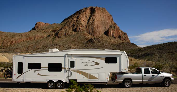
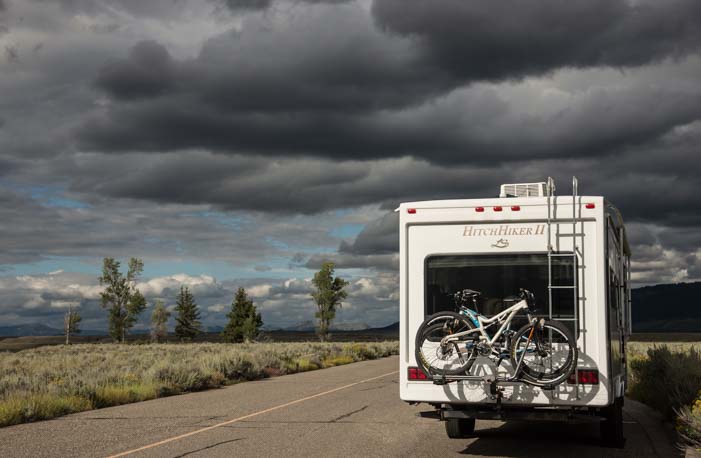
Here’s an example using a 435 amp-hour battery bank of four Trojan T-105 Reliant AGM golf cart style batteries as a starting point. This is our battery bank and is the maximum amount of battery capacity our 36′ fifth wheel trailer can carry comfortably due to weight and space constraints.
Using the Conventional Rule of Thumb above, the total wattage of the solar panel array would be approximately 450 watts. This is sufficient in the summer months in North America and might be sufficient at the equator or in the Land of the Midnight Sun in the winter months, but in our experience, our 490 watts of solar panels on our RV roof is inadequate during winters in the southern US when the sun is low in the sky, the days are short and winter storms create overcast skies for days on end.
Using the Two Step sizing method above instead, you would choose a solar charge controller that has a maximum current output of 25% of 435 amps = ~108 amps. The Outback FlexMax 80 is an 80 amp solar charger (relatively close to the 108 we’re looking for). It can support up to 1,000 watts of 12 volt solar panels (and more watts for higher voltage panels). Note that to get 80 amps of current, you’d need to have the solar panels facing 90 degrees to the sun, and the solar charge controller would need to be operating in the Bulk stage.
Sizing the solar charge controller this way, we are now looking at 1,000 watts of solar panels instead of the 450 watts that the Conventional Rule of Thumb came up with — twice as much!
This sizing method is probably overkill. However, it might make sense to size the panels and controller both ways and choose something in between. As I’ve said, in our case, 600 to 800 watts lying flat on our RV roof without tilting would be nice in winter.
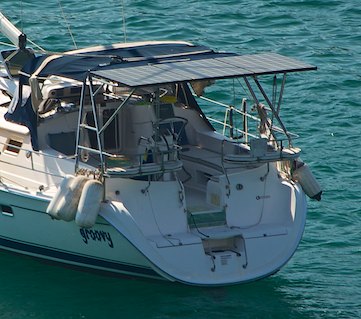
Our sailboat had 555 watts of solar power.
Note the shade on the panels from the mast and spreaders.
For us, on our boat (710 amp-hour battery bank) we could have used a 750 watt to 1,000 watt solar panel array instead of the 555 watts we had to run the systems we had on board, despite having ample sunshine throughout our cruise.
All of this is given here as food for thought. Sizing panels and batteries and solar charge controllers is all very flexible. More of everything is better, but the reality is that there are roof space constraints for the panels, and there are both weight and space constraints for the batteries, and those limitations will ultimately dictate your particular options for panels and batteries.
A truck camper and a Class A diesel pusher (or a Catalina 27 sailboat and a Nordhavn 62 trawler) obviously have different constraints and needs.
In very general terms, anything from a 450 amp-hour / 500 watt system to a 900 amp-hour / 1,200 watt system is fine for both boats and RVs that are used to boondock or anchor out for months on end, depending on whether you run electric refrigeration and how much you stay up at night watching TV with the lights on and/or stay home during the day using computers, electric appliances and power tools.
OUTBACK MX60 MPPT SOLAR CHARGE CONTROLLER
Now that we’ve seen the challenges that solar charge controllers face, let’s look at a specific example.
We installed an Outback MX60 MPPT solar charge controller in our fifth wheel trailer. It’s been in operation all day everyday that we’ve been in our trailer since we purchased it new in 2008. Since then, the Outback MX60 model has been discontinued and replaced by the new and improved Outback FlexMax 60 solar charge Controller.
BULK: Deliver maximum current until the Bulk voltage is reached.
ABSORB: Deliver as much current as necessary for the batteries to maintain the Absorb voltage. Transition to the Float stage when one of the following things happens:
- The charger has been in the Absorb stage for as long as it took for the batteries to reach the Bulk voltage.
- The current coming from the batteries has dropped below a certain level
If the sun fades and the controller can’t deliver enough current to keep the batteries at the Absorb voltage, extend how long the batteries stay in Absorb by the length of time the voltage fell below the Absorb voltage.
FLOAT: Deliver enough current to keep the batteries at the Float voltage.
EQUALIZE: Equalization voltage and time parameters are programmable, and equalizing can be done automatically or started manual. If Equalizing can’t be completed in one day, the batteries will resume equalizing the next day until the equalizing time has been completed.
Everything in the Outback MX60 charge controller (and the Outback FlexMax 60/80 Solar Charge Controllers) is programmable on a four-line LED menu driven display. You enter the battery type (Flooded, Gel, AGM) and that gives you default values for Bulk, Absorb and Float voltages. You can then override those values with values of your own if you wish.
So, how does this solar charge controller compare to a converter, inverter/charger or engine alternator?
If you compare the Outback MX60’s charging algorithm shown above to that of any of the artificially powered charge controllers described in the previous article, you can see just how very much more complicated this solar charge controller is. Here’s a little more detail:
SWITCHING FROM ABSORB TO FLOAT BASED ON TIME
The key part of any multi-stage charging algorithm is when to switch from the Absorb stage to the Float stage. (If you are unclear about those stages, read more here: RV and Maring Battery Charging Basics). All charging systems use TIME as a basic criteria. The question is how long?? Should the batteries stay in Absorb for 2 hours or 4 hours? Should it always be the same amount of time?
To be most amenable to the batteries’ needs, the state of charge of the batteries when they first start charging must be taken into account. If the batteries are nearly fully charged when charging starts, why keep them in Absorb for three hours? That’s like forcing down extra helpings of pie after a big Thanksgiving dinner. Maybe just a small piece is enough on a full stomach.
On the other hand, if the batteries are deeply discharged when the charging begins, they should stay in Absorb longer to make sure they really get full. If you didn’t nibble on hors d’oeuvres before dinner and you skipped lunch and breakfast, then extras helpings of everything at the Thanksgiving table might taste and feel great.
Outback tackles this conundrum by looking at how long it takes the batteries to reach the Bulk voltage. If they are well charged already, they’ll zip to the Bulk voltage quickly. In that case, they don’t need to stay in the Absorb stage for very long. On the other hand, if they are deeply discharged, it will take a long time for them to reach the Bulk voltage. In that case, they should hang out in Absorb for a long time until they are really and truly fully charged.
The way the Outback charge controllers accomplish this flexibility in the length of time of the Absorb stage is that they make the Absorb stage last for the same length of time as the Bulk stage did. If Bulk took 2 hours, then Absorb will last for 2 hours. If Bulk took 3 hours, Absorb will be 3 hours. Clever!
WHAT IF THE TARGET VOLTAGES CAN’T BE MAINTAINED?
Unfortunately, the sun isn’t all that consistent for such a basic algorithm, and there is more to it than just a simple one-to-one relationship between Bulk and Absorb. What makes this business tricky is that the sun may not allow the charger to hold the batteries at the Absorb target voltage once they begin Absorbing. For instance, in the middle of the Absorb stage, the sky might cloud over. The charge controller will respond by instantly opening the floodgates for the batteries so it can get the necessary current from the panels to keep the batteries at the Absorb voltage. But if the panels can’t deliver, there’s nothing the solar charge controller can do, and the battery voltage will fall below the Absorb voltage.
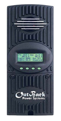
Outback FlexMax 60 MPPT Solar Charge Controller
In another scenario, someone in the RV or boat might turn on an electrical appliance that draws a lot of current — more than the panels can deliver — and this will temporarily lower the battery voltage below the target voltage. Running the vacuum or a hair dryer in addition to whatever else is running in the RV or boat might be just enough to draw more current from the batteries than the sun on the panels can produce.
In these cases, the solar charge controller will try to keep the batteries in the Absorb stage, but it’s failing. The thing is, if there isn’t enough current to keep the batteries at the Absorb voltage, are they really Absorbing? Not exactly. They’re getting as much current as possible, but the voltage has dropped below the Absorb stage threshold.
The Outback charge controllers view this as a kind of “timeout” period. So, for every minute of this “timeout,” they tack on a minute of extra time that the batteries must stay in Absorb before they switch to float.
For instance, if the batteries have been in Absorb for 53 minutes when the sky suddenly clouds over, the Outback charge controller will start counting how long the batteries stay below the Absorb voltage. If they stay below for 14 minutes, then once the sun comes back out and they get back to the Absorb voltage, they will need to stay in Absorb for an extra 14 minutes on top of the time period they were planning on (which is either the length of time that the Bulk stage took that day or a minimum amount of time programmed by the user). When they resume Absorbing, the Outback will resume counting from 53 minutes with a new target time that is 14 minutes longer than before.
This problem of the solar panels not being able to deliver enough current to keep the batteries at the target voltage exists in the Float stage as well as the Absorb stage. However, in the case of the Float stage there is no time consideration. Once they get into Float, the batteries will stay there (or attempt to stay there) until dark.
If you are confused, here is a real live example:
One day around noon our batteries had reached the Float stage (we’d gone to bed early the night before, so the batteries had charged up quickly). They were humming along getting about 4 to 10 amps or so to maintain a 13.5 Float Voltage with whatever stuff we had running in the RV (laptops, etc.).
I got out the vacuum, and when I turned it on, the charge controller jumped into high gear, demanding max output from the solar panels. The panels could deliver 25.6 amps, but that wasn’t enough to maintain the Float voltage of 13.6, and the battery voltage dropped to 13.1 until I finished vacuuming. Then everything went back to where it had been.
Lesson learned: use a broom not a vacuum!
You can see the display from the Outback charge controller here:

Outback MX60 Charge Controller display at midday with vacuum & computers running.
Note the batteries have dropped to 13.1 volts (below Float) and the current coming from the panels to the batteries is a huge (for “Float”) 25.6 amps to support the load in the RV. “F-MPPT” means “I’m in the Float Stage but I need max power ’cause I can’t maintain the Float Voltage.”
Even if the sun is out all day long and the batteries reach the Float stage, at the end of the day when the sun begins to set, the charger will no longer be able to hold the Float voltage. As it gets darker and darker, the charger will try valiantly to hold the Float voltage, but the battery voltage will drop lower and lower while the charge controller delivers less and less current.
Eventually, when it gets completely dark outside, no current will be going to the batteries at all. If the batteries were in Float before the sun went down, they will settle out at 12.7 volts, fully charged. If they never reached the Float stage, however, you’ve gotta cross your fingers for good sunshine tomorrow!
SWITCHING FROM ABSORB TO FLOAT BASED ON CURRENT
As I mentioned in the previous article in the description of the Xantrex Freedom 25 Inverter/Charger, a rule of thumb is to switch from Absorb to Float when the current that the batteries need to remain at the Absorb voltage drops below 2% of the amp-hour capacity of the battery bank.
For a 450 amp-hour battery bank, this would be 9 amps. For a 750 amp-hour battery bank, this would be 15 amps. So, for a 450 amp-hour battery bank, a reasonable time to switch from Absorb to Float is when the current drops below 9 amps. For a 750 amp-hour battery bank it is when the current drops below 15 amps.
The Outback FlexMax 60 (and 80) allow you to enter whatever number of amps seems right to you, whether it is 2% of your battery bank or some other number that you prefer.
Why is it important to switch from Absorb to Float when the amount of current the batteries need to remain at the Absorb voltage drops below a certain level?
The batteries may be nearly fully charged, but if the charging algorithm forces them to stay in Absorb for a set period of time — three hours for instance — they may need just 1 or 2 amps to maintain the Absorb voltage. It might be better for the batteries if they were allowed to slip back to the Float voltage at that point rather than forcing them to stay at 14.7 volts while accepting a minuscule amount of current until the 3 hours is up.
However, the reverse may also be true. There may be situations where you don’t want the batteries to be in the Float stage even though the charging current has dropped below 2% of the battery bank capacity. More on that further down.
WHAT HAPPENS AT NIGHT?
Because solar charge controllers operate 24/7, there are three more states that the Outbacks can be in:
- SNOOZING: The voltage of the solar panels is greater than the voltage of the batteries but there is no current coming in from them
- SLEEPING: The voltage of the solar panel array is less than the voltage of the batteries
- ZZZZZ…: The solar charge controller has been in the SLEEPING state for 3 hours or more
The controller has an algorithm for waking up as well. As the sun rises, once the voltage of the solar panels is more than 2 volts higher than the voltage of the batteries (i.e., the panels are at 14.7 volts or more if the batteries are fully charged at 12.7 volts), it looks for current coming in from the panels. If the current is still near 0, it SNOOZES in 5 minute intervals while it waits for the current to reach about an amp. Then it goes into Bulk and starts its work for the day. This happens each morning as the sky becomes light and the solar panel voltage rises from 0.
LOW LIGHT — FULL MOON and STREET LAMPS
It doesn’t take much light to bring a 400+ watt 12 volt solar panel array up to 15 volts. A full moon with clear skies may raise the voltage on the panels to this level, and parking under a bright street light will definitely do it. This is not enough light for the solar panels to generate current, but it can sometimes be enough to fool the charge controller that the sun might be about to rise and give it a sleepless night.
We have seen our solar charge controller pull an all-nighter as it alternated between SNOOZING and WAKE-UP all night long because the solar panel array was steady at 15 volts from a street light overhead while the batteries were at 12.7 volts.
The charge controller couldn’t start the real SLEEPING phase because the panel voltage was higher than the battery voltage. But there wasn’t enough light to generate any current either. So, the controller would WAKE-UP, discover there was no current coming in from the panels, and then it would go back to bed and SNOOZE a little longer. It would repeat this unfortunate cycle all night long, never getting into the really good 3 hour long ZZZZ… sleep stage (poor thing!).
On the other hand, while staying in the Catskill Mountains about 120 miles from New York City, I crept out at 2:00 in the morning to see how the charge controller was doing. The city lights kept the sky from being very dark, and the panel voltage was elevated slightly to 9 volts rather than the usual 0 volts we see in more rural areas. However, the batteries were more than 2 volts higher than that at 12.7, so the charge controller was well into its REM sleep phase, dreaming of sunny days. (Mark crept out to photograph the fireflies…a much better reason to climb out of bed at 2 am!!)
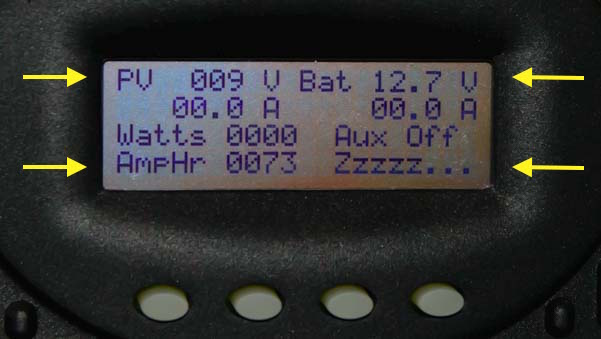
At 2:00 a.m. in the Catskills, the lights of NYC reflecting off low clouds raise the Panel Voltage to 9 volts. The previous day the batteries got 73 amp-hours of charge, so they are fully charged at 12.7 volts, more than 2 volts higher than the panels. The controller is sleeping soundly for 3 hours when it will check the panel voltage again.
XANTREX XW MPPT 60-150 SOLAR CHARGE CONTROLLER
We installed a Xantrex XW MPPT 60-150 Solar Charge Controller on our sailboat. Xantrex is now Schneider Electric, and this unit has been replaced with the Schneider Electric XW MPPT 60-150 solar charge controller. I don’t know if this is just a name change on the unit or if the design of the unit has changed in any way.
This solar charge controller is about the same size as the Outback but has a two line LCD display instead of four, so you have to scroll through the menus a bit to get the same info you can see at a glance on the Outback.
The challenge for us on our boat was that we had a smaller solar panel array than we needed for our typical daily power consumption due to our electric (DC) fridge and standalone freezer. 555 watts of solar power was not enough. So, we needed the charge controller to get the solar panels to provide as much current as possible everyday.
Unfortunately, it took us a while to realize that the factory default settings on the Xantrex charge controller were preventing the solar panels from providing as much current as they could.
The Xantrex charge controller came with a factory default setting to switch from Absorb to Float when the current being delivered to the batteries dropped below 2% of the amp-hour capacity of the battery bank, or 14 amps.

Our Xantrex XW MPPT60-150 charge controller on our sailboat
The problem was that once the current going to the batteries dropped below 14 amps, the solar charge controller put them into the Float stage. In the Float stage they needed much less current to maintain the Float voltage, usually around 5 amps. That’s a lot less than the nearly 14 amps they had been getting in Absorb!
What this meant was that even if the sun was shining brightly, the batteries were being given less current than the panels were capable of delivering because the solar charge controller had put them in the Float stage. The gatekeeper had closed the gate most of the way!
We would watch the system go into the Float stage at 1:00 p.m. and waste the best sunshine of the day sitting in the Float stage all afternoon charging the batteries with a lot less current than it would have if the controller were still in Absorb.
So, because the Xantrex charge controller had the programming option available, we programmed it to switch into Float when the batteries needed only 5 amps to maintain the Absorb voltage instead of the 14 amps that was 2% of our battery bank size. This way we were able to charge the batteries up by an extra 25-30 amp-hours each day.
However, the Xantrex controller didn’t make this programming option obvious. Rather than having an input parameter for the current at which to switch from Absorb to Float like the Outback models have, you could enter only the size of the battery bank. The controller would then calculate what 2% of that value was and would use that value to switch from Absorb to Float.
So, we had to fool the controller by saying our battery bank was only 250 amp-hours rather than the 710 amp-hours that it actually was. Then it would switch from Absorb to Float when the current dropped to 5 amps (2% of 250) instead of at 14 amps (2% of 710).
This also could have been alleviated by throwing the system back into a Bulk charge, and in our first days of working with this system, there were many times when I wished there were a setting to force the charge controller to put the batteries back in the Bulk stage whenever I wanted. But unlike the Outback solar charge controllers, this Xantrex model did not have that option.
So, as you can see, the Xantrex XW MPPT 60-150 Solar Charge Controller takes a slightly different approach to the challenges of solar charging than the Outback models do. Here are the details:
BULK: Deliver the maximum possible current to the batteries until they reach the Bulk voltage
ABSORB: Deliver as much current as necessary for the batteries to maintain the Absorb voltage. Transition to the Float stage when one of the following things happens:
- The current necessary to maintain the Abosrb voltage is 2% of the battery bank capacity
- The batteries have been in the Absorb stage for 2 hours (modifiable)
- The batteries have been at or above the Float voltage for 8 hours
FLOAT: Deliver enough current to the batteries to maintain the Float voltage.
EQUALIZE: The voltage and times for equalizing are user defined.
This charging algorithm is pretty straight forward, except for that odd 3rd way that the controller might switch from Absorb to Bulk. What’s going on there?
— What if the target voltages can’t be maintained — another technique!
That third trigger Xantrex uses for switching from Absorb to Float allows for the situation where the battery voltage has dropped below the Absorb voltage temporarily due to either clouds or shade or big loads in the RV or boat (vacuums or refrigerator compressors) drawing the voltage down for a while because the panels can’t deliver enough current. What it’s doing it that even if the batteries haven’t been at the Absorb voltage the whole time, as long as they have stayed above the Float voltage for at least 8 hours, they are considered ready to leave the Absorb stage and enter the Float stage.
Remember, the Outback solar charge controllers dealt with this same challenge of flaky sunshine by tracking how long the batteries fell below the Absorb voltage and then forcing the batteries to stay in Absorb for that same number of extra minutes to make up the lost time.
The Xantrex method is a little more simplistic than the Outback method, saying that as long as the battery voltage stayed above Float for 8 hours, they have been sufficiently charged and can switch to the Float Stage.
— Programming the charge controller for improved performance
As a recap, our goal was to keep the batteries in Absorb for as long as possible. So, I modified two of the Xantrex solar charge controller’s input parameters to allow this to happen:
- Pretend our battery bank was just 250 amp-hours instead of 710 so it would stay in Absorb down to 5 amps (modifying criteria #1)
- Increase the Absorb stage time limit from 2 hours to 8 hours (modifying criteria #2)
What these two programming changes ultimately did was they made the batteries stay in the Absorb stage for 8 hours, getting a healthy amount of current from the solar panels, unless the current happened to drop below 5 amps (2% of 250) before 8 hours was up.
This worked really well for 750 nights of anchoring out.
PROGRAMMING THE CHARGE CONTROLLER TO THE BATTERY MANUFACTURER’S SPECS
We were extremely cautious with the AGM batteries in our boat and did not want to modify the solar charge controller’s default voltage settings for AGM batteries since AGM batteries are sealed and they can’t be charged at as high a voltage as flooded batteries (this is explained in more detail in Part 1 of this series).
The default charging voltages for AGM batteries on the Xantrex XW MPPT-60-150 Solar Charge Controller are:
- Bulk: 14.3
- Absorb: 14.3
- Float: 13.4
* * * Lesson Learned * * *
Now that we have installed four Trojan T-105 Reliant AGM batteries in our fifth wheel and have been advised by the engineers at Trojan Battery to use Bulk and Absorb voltages of 14.7 volts on their AGM batteries instead of the 14.3 or 14.4 that most charging systems default to, I look back and realize I was probably too conservative with our boat’s AGM batteries.
If we had set the Bulk and Absorb voltage values to 14.7 instead of 14.4 (the setting I chose), then they would have charged faster (received more current from the charge controller) during those stages, and they would have won the daily race against the clock more easily. Obviously, more panels would have done the trick too, but finding unshaded deck space on a sailboat is tricky.
It only makes sense to program a battery charging system to the battery manufacturer’s specifications rather than assuming that the factory defaults on the charge controller are optimal. Afterall, charging system manufacturers — whether solar charge controllers, converters, inverter/chargers or engine alternators — will ALWAYS err far to the conservative side because they they are designing for a wide variety of battery brands and they don’t want to risk frying a customer’s batteries.
However, in the end, this might result in undercharging the batteries! Trojan Battery engineers have found that far more batteries die a slow death of chronic undercharging than a violent death of massive overcharging, so they prefer slightly higher charging voltages for their AGM batteries than are factory standard on many solar charge controllers, converters, inverter/chargers and engine alternators (with a caveat not to go to 14.8 volts or higher).
MORNINGSTAR TRISTAR TS-MPPT-60 SOLAR CHARGE CONTROLLER
We recently did a complete full-timer solar power installation on a friend’s motorhome. He specified the Morningstar TriStar TS-MPPT-60 Solar Charge Controller for his installation, so we had a chance to program it and work with it. This solar charge controller uses yet another methodology.

Morningstar TriStar MPPT 60 amp solar charge controller
This solar charge controller is programmed via dip switches and the charging stages are indicated by LED lights rather than a digital readout. You can also purchase the additional TriStar Remote Digital Meter that has a two line LCD display similar to the 2-line and 4-line displays on the Xantrex and Outback models described above.
Separating the charge controller from the display is a great idea. It allows you to install the display inside the RV or in the boat’s cabin where you can read it easily and mess with its buttons whenever you wish. Yet you can still place the charge controller itself right next to the batteries where it needs to be (the cable going from the batteries to the charge controller must be as short as possible).
Our friend did not purchase the remote meter, but we found the system was easy enough to set up without it. The dip switches were a clunky interface, but that would be improved with the buttons and digital display of the remote meter. The lack of a digital readout made it difficult to know the details about the voltages and currents of the panels and batteries in the system. However, our friend did not plan on programming the solar charger any further, and he already had a battery monitor in his coach, so he had a way to monitor the battery voltage easily.
Here are the details on the charging algorithm:
BULK: Deliver the maximum amount of current possible until the batteries reach the Bulk voltage.
ABSORB: deliver as much current as necessary to keep the batteries at the Absorb voltage until the following thing happens:
- 2 to 2.5 hours has gone by (depending on battery type)
If the batteries fell below 12.5 volts during the previous night, then extend the Absorb stage by 30 minutes.
FLOAT: Deliver as much current as necessary to keep the batteries at the Float voltage. If the batteries are drawn down below the Float voltage for an hour or more due to big loads in the RV or boat (vacuum, power tools, microwave) or due to sudden cloud cover, the charge controller will switch back to Bulk mode and start the cycle over again. If the batteries fell below 12.3 volts during the previous night, then the solar charger will not enter the Float stage the following day.
EQUALIZE: The voltage and duration of the Equalization stage is determined by the battery type selected and is started manually.
This is yet another creative approach to the various problems caused by the unreliability of sunshine. The idea of setting up the charging parameters today based on the lowest voltage the batteries reached overnight is cool, since that is truly the biggest determining factor for how much charging the batteries need right now.
However, note that there is no criteria for switching from Absorb to Float based on the current falling below a minimum value as with the other charge controllers. There is also no provision for lengthening the Absorb stage if the Absorb voltage can’t be maintained, although there is if the Float voltage can’t be maintained.
The Absorb, Float and Equalize voltages are assigned in this controller when you select the battery type. AGM batteries are assigned:
- Bulk/Absorb: 14.4
- Float: 13.7
There seemed to be an option to override those values with custom values, however, it wasn’t clear how to enter the actual voltages using the dip switches. The TriStar Remote Digital Meter might provide more programming flexibility.
The Morningstar does come with PC based software, and it is possible to connect the solar charge controller to your in-house ethernet network via the controller’s ethernet port or to connect it using a wireless router. However, for me, that adds a level of complexity that isn’t really necessary.
There are just a few parameters to enter on any charge controller, and just a few values to monitor, and those only need to be monitored occasionally. Having a menu driven screen interface built into the charge controller rather than getting my computer involved in the action is worth a lot to me.
FINAL NOTES
As you can see, there is a significant variation in how the different manufacturers of solar charge controllers tackle the challenge of creating an algorithm to charge the batteries, given the vagaries of sunshine. All of the solar charge controllers described here get the job done, it’s just that the methodology varies and the ease of use and programmability of the units differ.
If you want to get the most out of your solar charge controller, the most important thing is to know what your battery manufacturer’s recommended charging voltages and time limits are, that is, what their preferrred Bulk, Absorb and Float voltages are and how long they want the batteries to remain Absorb. Then program the solar charge controller accordingly.
The reason I chose the Xantrex XW MPPT-60-150 Solar Charge Controller for our boat rather than purchasing another Outback charge controller like the one in our RV (the nice new FlexMax 60 was on the market by then) was that the Outback has a fan in it. I was concerned that in the hot tropical climates where we would be sailing, the fan would likely run a lot and might fail. I didn’t want any moving parts! I chose the Xantrex because it is cooled by large cooling fins instead of a fan.
In hindsight, the Outback charge controllers are rated to operate at up to 104 degrees, and the cabin of our boat never got that high. Probably an Outback charge controller would have held up just fine. The Morningstar with its Remote Digital Meter is a neat idea for separating the charge controller and the digital display. However it does require a few more installation steps to mount the remote meter and run the cable from the charge controller location to the remote meter location. It also has a simpler overall charging algorithm, which could be a pro or a con depending on your preference.
__________________
The next — and final — article in this series takes a look at what happens when two battery charging systems are running simultaneously. That is, what happens if you have solar power and you plug into shore power or turn on the boat engine?
To continue to the next article in this series, click here:
Solar and Shore Power or Engine Alternator Battery Charging Combined
4-Part Series on RV and Marine Battery Charging Systems:
- RV and Marine Battery Charging Basics
- RV Converter, Inverter & Alternator Battery Charging Systems
- Solar Charge Controllers – Optimizing RV & Marine Battery Charging – this post
- Solar Power and Shore Power (or Engine Alternator) Combined
- Wet Cell vs. AGM Batteries - How do these batteries stack up and what's the best way to wire them?
- Solar Power Articles - Links to all the solar power related pages on this website
- RV Solar Power Made Simple - The basics - what goes into an RV or marine solar power installation and how it works
- Installing Solar Power on a Sailboat - Special considerations for solar power on a sailboat
- Solar Power Tutorial - A 4-part tutorial series on RV and Marine solar power
- Which Solar Panels Work Best? - Flexible panels or rigid? 12 or 24 volt? Monocrystalline or Polycrystalline??
- RV Electrical Power System Overhaul - Why we upgraded our systems and what we upgraded to
- Boondocking Lifestyle Tips - How to live off the grid in an RV (and be comfortable!)
- Boondocking Campsites: How to find free campsites - The resources we turn to
Subscribe
Never miss a post — it’s free!
Our most recent posts:
- Buckskin Mountain State Park – Fun on the Colorado River! 01/31/26
- How to Install Starlink Gen 3 in an RV? Use the Speedmount! 08/07/25
- Escape to Paradise – Rocky Mountain Magic! 08/01/25
- Is Forest River a Good RV? Well Built? Here’s Our Experience 06/20/25
- Sunset Crater Nat’l Monument – Lava & Camels at Bonito CG! 06/06/25