What happens when two RV or marine battery charging systems attempt to charge the batteries at the same time? The interactions between solar charge controllers, converters, inverter/chargers and engine alternators can be complex, and in our lives off the grid in a sailboat and RV, we have observed them working together in many different kinds of circumstances.
This page offers some insights into what goes on when two battery charging systems operate simultaneously, specifically: solar power and shore power, and solar power and an engine alternator. It is the fourth post in our series on RV and Marine Battery Charging Systems. The previous articles in this series are:
- RV and Marine Battery Charging Basics
- Converter, Inverter/Charger and Engine Alternator Battery Charging Systems
- Solar Charge Controllers – Optimizing Battery Charging from the Sun
This is a long post and you can navigate to the various sections using these links:
- What Happens When Two Charging Systems Operate At Once?
- Setting Common Baseline Charging Stage Voltages
- Effects of Wiring Voltage Loss and Differences in Calibration
- Lessons Learned From Our Engine Alternator and Solar Charge Controller
- Solar Charging And Electric Hookups
- Getting The Most Out Of A Backup Generator
- Final Notes
WHAT HAPPENS WHEN TWO CHARGING SYSTEMS OPERATE AT ONCE?
When two battery charging systems are working side by side simultaneously, each follows its own internal algorithms to get the job done. However, when this happens, and the two charging systems measure the battery voltage to determine which charging stage they should each be in, they don’t see a “real” value. They see an artificially elevated battery voltage due to the presence of the other charging system. This can throw one or the other or both systems off of their normal Bulk-Absorb-Float cycle.
Because solar charging systems operate 24/7, the most common scenario in which two charging systems work simultaneously is solar charging and some form of artificially powered charging, either a converter or inverter/charger when the RV or boat is plugged into shore power or the generator is turned on, or an engine alternator when the boat or motorhome is under way.
The bottom line with two charging systems working simultaneously is that each will do a little work, but one will do more work than the other. Higher end solar charge controllers are designed to ensure that the batteries are never overcharged. As explained in the previous post about solar charge controllers, they are the gate keepers for the solar panels and will reduce the current coming in from the panels to 0 amps if need be.
There are many factors to consider when running an artificially powered charging system alongside a solar charging system. And in reality, just letting the two systems do their thing without worrying about how they get along is probably fine. But for those who want to ponder the relationships, here are some things we’ve learned.
SETTING COMMON BASELINE CHARGING STAGE VOLTAGES
In order for all the charging systems on an RV or boat to work together truly harmoniously, it is helpful for the voltages at which the systems change charging stages to be the same across all the systems. For instance, each charging system should be set up with one common set of voltages similar to the following:
- Bulk 14.7 volts
- Absorb 14.7 volts
- Float 13.5 volts
If these terms are confusing, have a peek at Battery Charging Basics.
Obviously, these voltages should be whatever values you have determined are optimal for your battery type. Unfortunately, some charging systems don’t allow you to enter specific voltages, so you may be stuck with whatever defaults the manufacturer chose or whatever “set” of voltages they provide that is closest to the values you want.

Soaking up the sun:
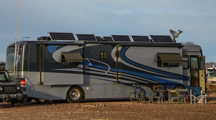
600 watts of flexible solar panels we installed on a friend’s motorhome roof.
As you can see, if one system has an Absorb target voltage of 14.7 volts and another has an Absorb target voltage of 14.1 volts, there is going to be a conflict. What will happen is that the system that is aiming for the higher voltage will win out and raise the batteries to or towards the higher voltage. The reaction of the other system will depend on how it was designed to handle a situation where the battery voltage is higher than the stage it was in. This is true for all the target voltages (Bulk, Absorb and Float).
Similarly, all the charging systems on the RV or boat should be set up with the same algorithm for switching from one stage to the next. However, as shown in the posts about converters, inverter/chargers and engine Alternators and about solar charge controllers, this is not possible, because every product made by the many manufacturers who build these things has a unique charging algorithm.
There are some similarities, however. All multi-stage charging systems remain in the Bulk stage, pouring the maximum current they can into the batteries, until the Bulk voltage is reached. Then they switch to the Absorb stage. However, no two charging systems use the same criteria to exit the Absorb stage to go into Float. The Float stage is also handled differently by different chargers and manufacturers.
EFFECTS OF VOLTAGE LOSS IN THE WIRING
Every RV and marine battery multi-stage charging system monitors the battery voltage to decide which stage to be in. How and where this voltage is measured and how each device is internally calibrated can make quite a difference.
For instance, the solar charge controller in a sailboat may be located as much as 20′ from the battery bank if the batteries are strung out from bow to stern in the bottom of the bilge and the charge controller is mounted in an aft compartment. Unless the charge controller is connected to the batteries with fairly beefy wires, there will be some voltage loss between the batteries and the charge controller, and the charge controller will get inaccurate readings of what the battery voltage actually is.
This can happen even if the distance is just 10′ but the wire used is too small for that distance. It can also happen if the engine alternator or the converter or the inverter/charger is a long distance from the batteries. Wire gauge sizes, distances and percentages of voltage lost are given in the following chart:
Wiring Gauge vs. Voltage Loss Chart
EFFECT OF DIFFERENCES IN CALIBRATION
Higher end solar charge controllers are complex pieces of electronic engineering that are likely to be calibrated pretty well coming out of the factory. However, a cheapie single stage converter, like the factory installed units that come with so many RVs, may not be calibrated as well, and may be off in its measurement of the battery voltage by a tenth of a volt or more. Likewise with a simplistic engine alternator.
It was a big surprise to me to read in the user manual for our boat’s engine alternator/regulator (a Balmar ARS-4 multi-stage regulator) that the voltages may be off by +/- 3%. That means that a target Bulk voltage of 14.4 volts could vary between 14.0 volts and 14.8 volts. Hmmm. Not a lot of precision there!
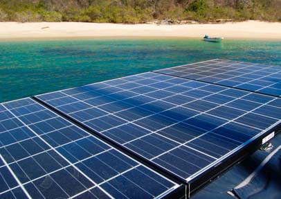
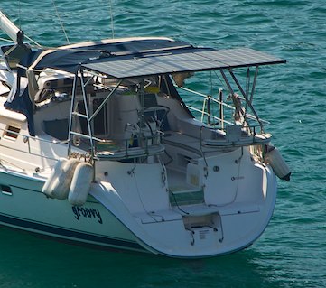
Our solar panels catch some tropical rays on the back of our sailboat during our cruise in Mexico.
If the two charging systems that are working simultaneously are detecting different voltages on the batteries — for instance, the solar charge controller is measuring the batteries to be 14.5 volts while the converter is measuring them to be 14.7 volts — they will each react according to their own internal charging algorthims.
For instance, say both the solar charge controller and converter are in Bulk mode, trying to attain a voltage of 14.7 volts before switching to Absorb. When the batteries reach 14.7 volts according to the converter, the converter will think they have achieved the Bulk voltage already and will switch to the Absorb stage, while the solar charge controller will remain in the Bulk stage because it sees only 14.5 volts, and it will continue aiming for 14.7 volts, according to its internal measurements and algorithm.
What does this mean? It simply means that the solar charge controller will continue to let as much current in from the solar panels as they can produce while the converter will already be backing off how much current it puts into the batteries to hold them steady at what it perceives to be 14.7 volts (and which the solar charge controller sees as 14.5 volts). Not a big deal. The solar charge controller will keep pushing while the converter keeps backing off, and the job will eventually get done.
LESSONS LEARNED FROM OUR ENGINE ALTERNATOR AND SOLAR CHARGE CONTROLLER
The most challenging relationship we’ve had between charging systems was on our sailboat, and it was the one that forced me to investigate this whole business more deeply and to learn how to program a solar charge controller — and to discover, in the process, the value of programming one!
The two systems were our Balmar ARS-4 engine alternator/regulator and our Xantrex XW-MPPT-60-150 solar charge controller. The charging algorithms for these systems are described in detail here (for the alternator) and here (for the solar charger).
When I first observed them working together, I noticed two things right away.
1) Whenever we turned on the engine, the solar charge controller went into the Float stage soon afterwards.
2) Once the solar charge controller was in the Float stage, if we turned the engine off, it remained in the Float stage, even if the batteries hadn’t been fully charged by the engine alternator.
For instance, if the solar charge controller had been in the Absorb stage when we turned the engine on, and then we ran the engine for just 15 minutes and turned it off (not nearly long enough to charge the batteries), the solar charge controller would wind up in the Float stage and remain there for the rest of the day, depriving the batteries of a proper charge.
Engine Alternator Causes the Solar Charge Controller to Switch from Absorb to Float
The thing about batteries in a complex vehicle like a motorhome or a boat is that they are running many different systems that are continually turning on and off. In the case of our boat, when we were underway, any or all of our big systems might be in use at any one time: fridge and freezer compressors, radar, chartplotter, autopilot, anchor windlass, and even the microwave.

100 amp Balmar diesel engine alternator
Worst case, all of those things might be on at once for several minutes as we raised or lowered 200′ of stainless steel anchor chain with a 60 lb. anchor attached to the end of it (well, maybe not the microwave!).
Plus, there was no guarantee we’d run the engine long enough for the alternator to go through its Bulk and Absorb stages and charge the batteries completely.
We might run it for as little as a few minutes while moving from one anchoring spot to another, or for half an hour while we motored out of the bay to go daysailing.
We wouldn’t want to idle the engine at anchor just to charge the batteries, because the engine RPMs have to be fairly high for the alternator to generate a good charging current. These high RPMs happen naturally while driving the boat, but unfortunately, conventional wisdom says that revving the engine to high RPMs while not in gear (i.e., without a load on it) risks glazing the cylinder walls.
Besides it being random as to how long we might run the engine, it was also random as to what state the solar charge controller would be in when we started the engine up.
We might start the engine in the dark to raise the anchor, and in that case the solar charge controller would be asleep. Or we might do it early in the morning when the solar charge controller was in the Bulk stage and gamely trying to get whatever current it could from the wimpy sun on the horizon. Or we might do it later in the day when the solar charge controller was in the Absorb stage and cranking away.
We used a clamp-on ammeter to find out exactly what was going on at various points in the system. We put it around the alternator’s battery cable to see how much current the alternator was putting into the batteries. We also used it on the solar charge controller’s battery cable to verify that the current it displayed on its LCD screen was correct (it was).

The alternator is pouring 77.9 amps into the batteries – WOW!!
Whenever we turned on the engine, regardless of what the solar charge controller was doing, the engine alternator would immediately go into the Bulk stage and dump as much current into the batteries as they needed to reach the alternator’s Bulk voltage.
If the solar charge controller had been in the Bulk stage already, its job would suddenly become much easier as it got a huge boost from the alternator.
If it had been putting 21 amps into the batteries and had been slowly raising the voltage towards 14.4 volts (the setting we had for the boat’s batteries), the engine alternator might contribute another 40 amps for a while, getting the batteries up to the Bulk voltage a whole lot faster than if the solar panels had continued working by themselves.
If the solar charge controller had been in the Absorb stage already, putting something like 18 amps into the batteries to hold the Absorb voltage of 14.4 volts, the engine alternator would begin its own Bulk stage regardless, and it would remain in the Bulk stage for 36 minutes as it followed its own internal algorithm.
The solar charge controller would react by backing off and delivering less current.
To make things more complicated, as these two systems worked through their charging stages, the loads on the batteries would be fluctuating widely as Mark and I went about our business of living on a boat.
If the fridge and freezer compressors were both running, and the autopilot was maintaining our course and the radar and chartplotter were on and we were making burritos in the microwave, the batteries would need a lot of current.
However, if neither compressor was on and someone was hand steering the boat, etc., then the batteries would need a whole lot less current. During those lulls in current demand, the solar charge controller would suddenly scale things way back and put just 8 or 9 amps from the panels into the batteries.
As soon as that happened, the solar charge controller would suddenly switch to the Float stage!
Huh?!
After some sleuthing, as described in the previous post, I realized that the charge controller was switching from Absorb to the Float stage because the current needed to maintain the Absorb voltage had dropped below 2% of the capacity of the battery bank.

In Tangolunda Bay (Huatulco, Mexico) we motored back and forth across the bay every few days to anchor out of the swell as it changed its flow.
Since I had entered the true value of the battery bank (710 amp-hours), the controller switched from Absorb to Float when the current dropped below 14 amps (2% of 710).
So, I lied to the controller and told it the battery bank was just 250 amp-hours. Then it would remain in Absorb down to 5 amps.
What I found (by trial and error) was that the solar charge controller pretty much always needed more than 5 amps when it was in Bulk or Absorb.
I don’t know why the alternator didn’t produce that last 5 or so amps on its own, but I suspect it was because the alternator’s Absorb voltage was set to 14.2 volts while the solar charge controller’s Absorb voltage was set to 14.4 volts (the alternator had “sets” of values for the three target voltages, and 14.2 volts for Absorb was in what I felt at the time was the most appropriate set).
The Solar Charge Controller Gets Stuck in the Float Stage
The second problem I encountered was that in the event that the solar charge controller went into the Float stage prematurely, then, after the engine was turned off it would remain there until the next morning.
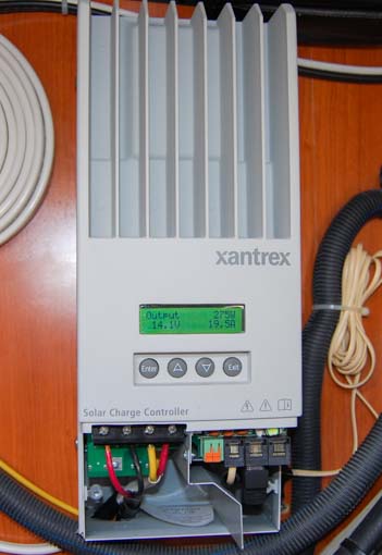
Xantrex solar charge controller
(bottom plate removed)
Yet the batteries may not have been fully charged by the alternator, and they may have really needed to remain in Absorb with the solar panels charging them at a fast clip for another hour or two.
In this case, the solar charge controller needed either to resume the Absorb stage or cycle back through the Bulk stage as soon as the engine was turned off.
The only way the Xantrex XW MPPT 60-150 would cycle back through the Bulk stage is if the battery voltage dropped below a certain level.
I experimented with different voltages. The Float voltage was 13.4 volts, so if I set the “ReBulk” voltage to be 13.5 volts or higher, then the charge controller would never get into the Float stage at all, because it would keep cycling back to Bulk.
According to the user manual, this is actually a valid way to operate this solar charge controller, and they even provide a programming parameter that sets the charge controller up to be a “two stage” charger that has no Float stage and has just the Bulk and Absorb stages.
I wasn’t comfortable with not having a Float stage (although in hindsight that probably would have been just fine given the intermittent heavy loads that were on the batteries all day long). In the end, I settled on a ReBulk value of 12.9 volts.
So, if the solar charge controller was in the Float stage after the engine was turned off, and a big load came on some time afterwards that drew the battery voltage down from 13.4 volts to below 12.9 volts (microwave plus fridge and freezer, for instance), then the solar charge controller would cycle back through the Bulk stage and start the charging cycle all over again.
Programming For Storage
Periodically, we left the boat for a month or several months at a time when we traveled inland or went back to our RV for hurricane season. Since the fridge and freezer would be turned off, and there would be no loads on the batteries at all, I would undo these two programming changes. I would reprogram the solar charge controller with the true size of the battery bank so it would switch from Absorb to Float at 14 amps rather than 5, and I would change the “ReBulk” voltage back to 12.5, the factory default.
SOLAR CHARGING AND ELECTRIC HOOKUPS
Sometimes There Are Good Reasons Not To Plug In!
Solar power is free, however, the electricity from shore power hookups may not be. If your shore power electricity is “free” (i.e., built into the overnight fee you are paying for your RV site or boat slip), then it doesn’t really matter which charging system is dominant.
If you have metered electricity (a common situation if you are renting your RV site or your boat slip on a monthly, seasonal or annual basis), and you are paying for your electricity, then you may want to ensure that your solar charger is running the show and doing the bulk of the work while your converter or inverter/charger is playing second fiddle.
One easy way to do this is just to flip off the electric switch on the shore power post. Flip it on only as needed when the batteries get low and need a boost.
We did this a lot when we lived on our sailboat. We lived at a slip in Paradise Village Marina in Puerto Vallarta, Mexico, as well as at slips at Hotel Coral and at Cruiseport Marina in Ensenada Mexico for months at a time without plugging in the shore power cord at all. During hurricane seasons, we also left our boat in a slip in Marina Chiapas for seven months without plugging it into shore power.
It was nice when we settled up the bills for these places at the end of each stay to have a big ol’ “$0” on the line item for electricity.
What Happens If You DO Plug In?
If your RV or boat is plugged into shore power, and the switch at the post is turned on, it is hard to get the solar power system to be dominant because its power source is flakey (as explained here).
We plugged our sailboat into shore power for several months while we lived aboard at Kona Kai Marina in San Diego at the end of our cruise.

Schneider Electric (Xantrex)
2500 watt Freedom inverter / charger
Our Xantrex inverter/charger went through the Bulk and Absorb stages the first time we plugged in, and then it remained in the Float stage forever after (except when we unplugged to go day sailing and plugged back in again upon returning)!
Each morning when our Xantrex solar charge controller woke up, it zipped through the charging stages and went into the Float stage after just a few minutes, because it saw the batteries were already fully charged.
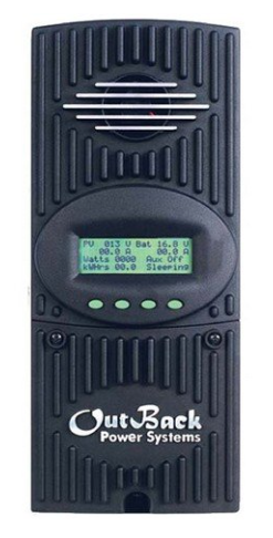
In our RV, we plugged into shore power for 48 hours during rainy and stormy skies while we stayed at Narrows Too RV Resort in Maine. It was overcast when we plugged in. Our Outback solar charge controller was in the Bulk stage putting about 6 amps into the batteries at around 13.9 volts (it was aiming for 14.7 volts).
Ordinarily, since we live a solar power only lifestyle, our Outback solar charger is set up with Bulk and Absorb values of 14.7 volts, a minimum Absorb time of 2 hours and a maximum Absorb time of 4 hours. However, our Iota DLS-90 / IQ4 Converter has a fixed (non-modifiable) Bulk voltage of 14.6 volts and Absorb voltage of 14.2 volts and Absorb time of 8 hours.
I temporarily changed the solar charge controller to have Bulk and Absorb voltages that matched the converter, and minimum and maximum Absorb times of 0 hours so it would remain in Absorb only as long as it took to get to Bulk (the charging algorithm of the Outback solar charge controller is explained in detail here).
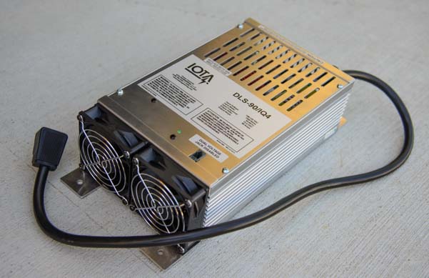
Iota DLS 90 IQ4 Converter and smart charger ready for installation in our RV
As soon as we plugged in, the converter began dumping 49 amps into the batteries which zoomed the battery voltage up to the converter’s Bulk stage value of 14.6 volts. Then it backed way off to 30 amps, then 20, then 15 as it held the converter’s and solar charger’s Absorb voltage of 14.2 volts (our new Trojan Reliant AGM 6 volt batteries charge up extraordinarily quickly!).
The Outback solar charge controller responded by putting in a few amps at first, but then it displayed “Bat Full” and went to sleep!
From there, the Outback solar charge controller went through its usual Sleeping and ZZZZ stages as the Iota DLS-90 / IQ4 Converter quietly slipped from Absorb (14.2 volts) to Float (13.6 volts). When the Outback solar charge controller went through its wakeup sequence after being in the ZZZZ stage for 3 hours, it saw the batteries were fully charged, so it rolled over and went back to sleep in the ZZZZ mode.

We catch our RV’s solar charge controller sleeping on the job at midday!
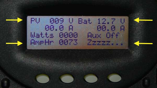
The solar panels are in full sun and are at 68 voltsThe converter is in control and has elevated the batteries to 13.5v
But the controller sleeps soundly as 0 amps go from the panels to the batteries!
In fact, the whole rest of the time we were plugged into shore power, the Outback solar charger stayed in the ZZZZ mode, even in bright afternoon sunshine. Every 3 hours it would lazily open its eyes, yawn, look at the state of the batteries, see that they were fully charged and go right back to dreamland in the ZZZZ mode.
- The Xantrex solar charge controller on our boat reacted to the presence of the Xantrex inverter/charger by going into the Float stage all day long and sleeping at night.
- The Outback solar charge controller on our RV reacted to the presence of the Iota converter by going to sleep and staying asleep both night and day.
Do The Different Charging Voltages Have To Match?
No. On another occasion, while getting repairs done at an RV dealership, we plugged in our trailer for an afternoon while it was out on the lot next to the building on a cloudy day. The solar charge controller was putting in 6 amps at 13.8 volts in the Absorb stage (trying to keep the batteries at 14.7 volts) at mid-afternoon.
As soon as the shore power cord was plugged in, the converter began dumping 55 amps into the batteries and the battery voltage zoomed to 14.6 volts. The solar charge controller kept putting in around 6 amps.
For the next few minutes, the total current going into the batteries dropped from 61 amps to 33 amps and then settled there. If the solar charge controller could put in 8 amps, as the sky lightened, the converter put in 25 amps. If the solar charge controller could put in only 2 amps as the sky darkened, the converter put in 31 amps.
Suddenly, the converter switched to its Absorb stage where it holds the batteries at 14.2 volts, and the total current going into the batteries dropped to 20 amps. The solar charge controller was still in its own Absorb stage where it wanted to hold the batteries at 14.7 volts, so it kept putting in as much current as it could (5 to 8 amps and even as high as 12 when the sun came out for a few minutes) while the converter made up the difference, keeping the total at around 20 amps.
We didn’t stay plugged in long enough to see the solar charge controller switch to Float (the converter stays in Absorb for 8 hours), but at that point the converter would have held the batteries at 14.2 volts while the solar charge controller wanted them at 13.5 volts. It also would have been dark, so the converter would have been in complete control and the solar charge controller would have gone to sleep.
GETTING THE MOST OUT OF A BACKUP GENERATOR
If you are using a generator to give the batteries a boost of charge because you’ve been in cloudy conditions or don’t have enough solar power to run everything on board indefinitely, then you’ll want the generator to charge the batteries as quickly as possible, saving you a few dollars in fuel (gas or diesel) and saving yourself from the loud noise and obnoxious fumes of the generator itself.

Yamaha 2400i generator — our backup
In essence, the goal with a generator is to run it for as short a time as possible to get the batteries charged up.
With solar power, at the end of the day, before nightfall, the batteries are in their most charged state.
During the evening and into the darkest hours of the night, the batteries get depleted from running the lights, the TV, the computers, the microwave and whatever else your household uses until bedtime.
By dawn, the batteries are at their lowest state of charge. This is also a time when the sun is low in the sky and the solar panels are operating weakly and producing minimal current.
Early morning is the ideal time to turn on the generator!
An Example of Generator Use at Midday versus Dawn
The first time we fired up our generator to charge our batteries via the Iota DLS-90 / IQ4 converter, we’d had several overcast days in a row. It was mid-afternoon, and the batteries were fairly depleted from days of cloudiness. However, they had already gotten about 25 amp-hours of charge during the morning and noon hour, so they weren’t as depleted as they had been at dawn.
The solar panels were limping along in the Bulk stage with the batteries at about 13.5 volts. The solar charge controller was aiming at a Bulk voltage of 14.7 volts and the panels were valiantly trying to produce enough current to get there, but all they could muster was about 6 amps. It wasn’t likely the batteries would reach the Float stage before dark.
As soon as we turned on the generator, the the Iota converter went into the Bulk stage and began delivering about 60 amps to the batteries. It quickly got them up to 14.6 volts and switched to Absorb, dropping to about 20 amps. Great! But this converter is capable of putting 90 amps into the batteries, so why run it when Bulk mode delivers just 20 amps?

We let the solar panels do their job during the day.
We decided turn off the generator and let the solar panels do whatever they could for the rest of the day.
Early the next morning when the batteries were depleted from several days of inadequate charging plus a night of activity in the RV (they were down to about 12.3 volts), we fired it up again.
I did not modify the settings on the Outback solar charge controller to match those of the converter because we were just going to run the generator for a few hours and probably wouldn’t need it again for a few months.
This time the converter rolled up its sleeves and got to work, pumping 67 amps into the batteries as it aimed for its target Bulk voltage of 14.6 volts. The solar charge controller was in Bulk mode too and was busy putting in 1-2 amps of its own (it was early morning), and with the converter’s assistance, it briefly hit 14.7 volt Bulk target and switched to Absorb.
With both the converter and solar charge controller operating in the Absorb stage, the converter dropped the current to maintain the target Absorb voltage. The solar charge controller could still bring only 1-2 amps to the party due to the low light, so the converter was in control and doing virtually all the work.
We shut off the generator off after about two hours and let the solar charge controller take over. Now that the batteries were partially charged up, the solar charge controller was able to get the batteries up to its Absorb voltage target and finish the job, even in the overcast conditions, getting the batteries through its Absorb stage and going into the Float stage for the first time in a few days.
FINAL NOTES
So, you can see, there are many ways to charge RV and boat batteries and many things to consider. Of course, it’s easy enough to leave the various charging systems at their factory settings after installing them, and there is nothing wrong with that!
But if you want to understand your system and get the most out of it — especially if you are using solar power and end up running a second charging system in conjunction with your solar power system — you may want to dig into the nitty gritty details buried in the user manuals and figure out what the charging algorithms are and how to program each system with the parameters that make the most sense for you.
All battery charging systems for mobile installations like RVs and boats have become increasingly more sophisticated over the years. A quick review of the older systems described in detail in the previous posts here and here show how the engineers designing these systems have become more and more knowledgeable about the real world applications of their products and what conditions they might encounter as they interact with other charging systems.
As the years go by from here forward, more and more solar charge controllers, inverter/chargers, converters and engine alternators will be designed with the understanding that they may not be the only charging system operating in the RV or boat.
This was the last article in our series on RV and Marine Battery Charging:
-
1. RV and Marine Battery Charging Basics
2. Converter, Inverter/Charger and Engine Alternator Battery Charging Systems
3. Solar Charge Controllers – Optimizing Battery Charging from the Sun
4. Solar Power and Shore Power (or an Engine Alternator) Combined – This post
- Wet Cell vs. AGM Batteries - How do these batteries stack up and what's the best way to wire them?
- Solar Power Articles - Links to all the solar power related pages on this website
- RV Solar Power Made Simple - The basics - what goes into an RV or marine solar power installation and how it works
- Installing Solar Power on a Sailboat - Special considerations for solar power on a sailboat
- Solar Power Tutorial - A 4-part tutorial series on RV and Marine solar power
- Which Solar Panels Work Best? - Flexible panels or rigid? 12 or 24 volt? Monocrystalline or Polycrystalline??
- RV Electrical Power System Overhaul - Why we upgraded our systems and what we upgraded to
- Boondocking Lifestyle Tips - How to live off the grid in an RV (and be comfortable!)
- Boondocking Campsites: How to find free campsites - The resources we turn to
Subscribe
Never miss a post — it’s free!
Our most recent posts:
- How to Install Starlink Gen 3 in an RV? Use the Speedmount! 08/07/25
- Escape to Paradise – Rocky Mountain Magic! 08/01/25
- Is Forest River a Good RV? Well Built? Here’s Our Experience 06/20/25
- Sunset Crater Nat’l Monument – Lava & Camels at Bonito CG! 06/06/25
More of our Latest Posts are in the top MENU above.
More of our Latest Posts are in the MENU. New to this site? Visit RVers Start Here to find where we keep all the good stuff. Also check out our COOL NEW GEAR STORE!! *** CLICK HERE *** to see it!


