RV Solar Upgrade with Renogy and Go Power – QUICK & CHEAP!

We recently did an RV solar upgrade project that proved to be quick, easy and cheap. We spent just $480 to jump from 190 watts of power to 570 watts, more than enough for our boondocking off-the-grid RV lifestyle. PLUS it took less than three hours to install. What a great bang for the buck!
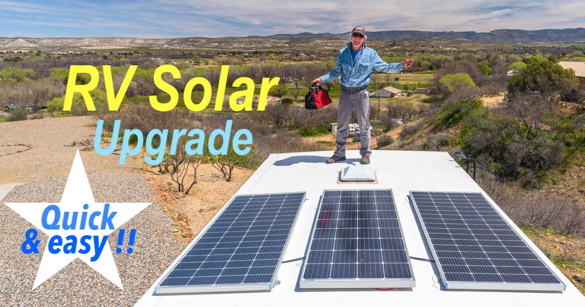
RV Solar Upgrade - CHEAP & EASY with Go Power + Renogy

.

Our Genesis Supreme 28CRT fifth wheel toy hauler came with a small factory-installed Go Power RV solar power system that included a single 190 watt solar panel, a 1500 watt pure sine wave inverter and a 30 amp PWM solar charge controller connected to four dealer-installed Group 24 12-volt wet cell batteries with a capacity of 280 amp-hours.

Factory-installed RV solar power systems like this one are now a common option on many new RVs, and Go Power (a subsidiary of Dometic) is often the brand that RV manufacturers use.

Although none of the components in the system are “best of breed,” the Go Power system worked fine for us as we boondocked every night for four months last summer. As the months wore on towards the Fall (and away from the summer solistice), however, the batteries struggled more and more each day to reach full charge. In the last few weeks in late August and September they never did.

Fortunately, the Go Power 30 amp solar charge controller that came with this system can handle up to 600 watts of solar panels, so an RV solar upgrade was possible without replacing the charge controller!

As we contemplated doing an RV solar upgrade all last summer, the debate was: do we ditch the whole factory installed system and replace it with top of the line components or do we simply add some more panels to the existing system?


How much solar power do you really need when you live in an RV?

Answering that question is really important because it’s incredibly easy to end up installing a far bigger and fancier system than you actually need after hearing people discussing their mammoth systems around the campfire.

Just because a friend has a huge system doesn’t mean it will make sense for you to break the bank to install one too!

How big an RV solar power system you need depends entirely on how much power you use in your day-to-day RV lifestyle and how often your boondock.

We boondock every night, but we don’t use much power. Also, since we are now seasonal travelers instead of the full-timers as we used to be, we travel primarily in the summertime when the sun is high in the sky at a good angle for the solar panels and the days are long, allowing the solar panels to work for a few extra hours.

Our primary power use is our two laptops (which we use a lot), the water pump, and the interior lights for an hour at night (we go to bed early). We don’t watch TV and we rarely use the microwave or hair dryer.

Running the air conditioning on battery power is not possible for any but the most massive RV solar power charging systems and battery banks, so it’s not part of the equation for most people. We rely on the generator for running our a/c.

With our traveling lifestyle of minimal power use, we happily lived on 480 watts and 555 watts in our trailer and sailboat respectivlely for 13 years. That was plenty of power for us except in the dead of winter when the sun was low in the sky (poor angle to the solar panels) and the days were short.

RV solar panel installation using Go Power and Renogy panels

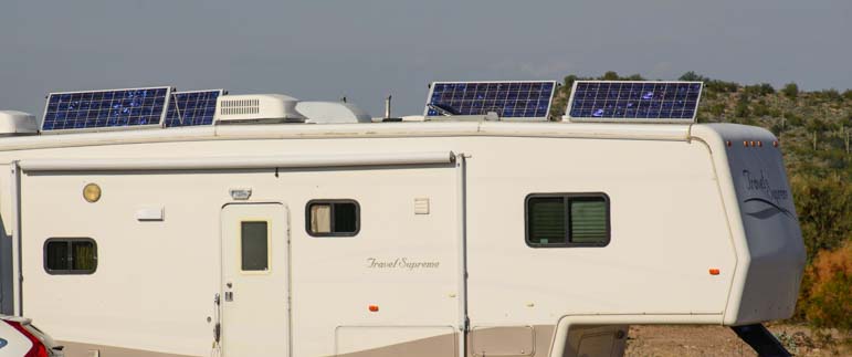
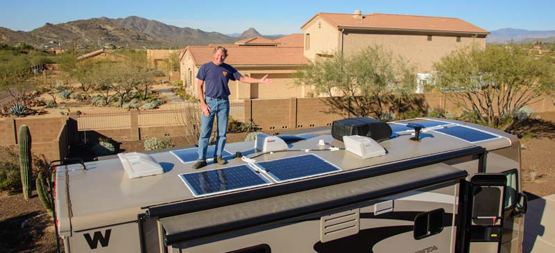
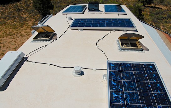
Our toy hauler had one factory installed solar panel (center).
An easy RV solar upgrade with two more panels tripled our battery charging capacity!

When we did those installations in 2008 and 2010, they were considered to be sizable for a boat or an RV. Seeing a rig with 1,000 watts on the roof in those days made everyone’s head turn while they mouthed the word, “WOW!”

However, by today’s standards, we had small systems on both our RV and sailboat! The third owner of our boat Groovy upgraded the solar panels to 930 total watts instead of the original 555 watts.

Last year, we met a full-timing family who had 3,500 watts of solar power on the roof of their 44′ toy hauler. They also had two huge Victron solar charge controllers (the panels were wired in two separate arrays) and they had a massive bank of lithium-ion batteries in the basement.

They could run their air conditioning on battery power all day and they had a full-size residential refrigerator to boot. They liked to keep their TV on all day long and the kids spent hours watching videos on their iPads. The kids also did homework on their laptops and everyone in the family had had phones and laptops to charge. They also had several internet access devices that gave them a total of 500 GB of data each month. They used it all and sometimes fell a little short by month’s end!

So, the size of the system you need depends entirely on how you live your RV lifestyle.

We knew when we bought our toy hauler last year that 190 watts wouldn’t be enough for us long term, but we didn’t have time to fuss with and do an RV solar upgrade before starting our summer journey. We were also curious to see how it performed right from the factory.

The solar charge controller is a lower end PWM unit (Pulse Width Modulation) rather an MPPT (Maximum Power Point Tracker) type of controller that eeks out more power from the panels. We wondered if the system would work at all. We were pleasantly surprised that it worked quite well and did the job all summer long, although our batteries did get down to 11.9 or 12.0 volts on quite a few colder mornings at summer’s end, much lower than we’ve ever seen our house batteries before.
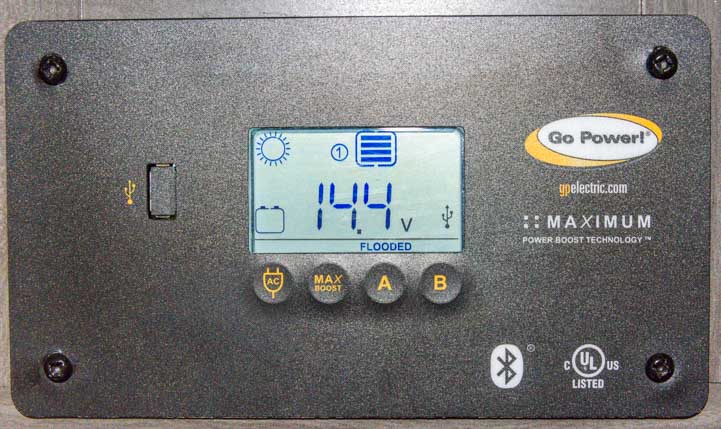
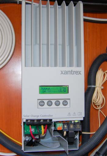
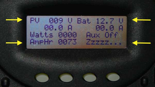
Go Power 30 amp PWM solar charge controller

Go Power 30 amp PWM solar charge controller mounted on a wall inside the rig.

Ultimately, we decided the simplest and most stress-free RV solar upgrade we could do would be to add more solar panels and leave all the other components alone.

RV Solar Upgrade – Adding New Solar Panels – Wired in Parallel or in Series?

The Go Power solar panel that came with the rig is a 12 volt 190 watt panel. Although the Go Power 30 amp solar charge controller can handle 600 watts of power coming from the panels, it is unable to operate on anything but 12 volts. Fancier charge controllers can work with the panels at 24, 36 or 48 volts and then step down the voltage to 12 volts to charge the batteries.

This limitation meant we didn’t have the option of using 24 volt panels which are generally cheaper per watt. Also, it meant that the new panels would have to be wired in parallel with the existing panel to keep them all at 12 volts rather than having the option of wiring them in series because it would put the solar array at 36 volts.

As a side note, even though we didn’t have a choice in this case, the decision whether to wire the solar panels in parallel versus in series is a matter of how much shade the panels might encounter and how long the cable runs will be versus the guage of the wire.

When solar panels are wired in series, if one panel gets shaded, all the panels reduce their power output dramatically. Also, the voltage of the panels is cumulative while the current stays the same. That is, three 12-volt panels will be at 36 volts but the current running in the wires will be the nominal current of a single panel, for instance, 10 amps.

When solar panels are wired in parallel, if one panel gets shaded, the others continue to produce power at their normal rate. So, in a three panel array, if one panel drops out you still get 2/3 of the power because the other two panels are still working. Also, the voltage of the panels remains the same but the current is cumulative. That is, three 12-volt panels will be at 12 volts but the current will be additive, or 30 amps.

The more current there is in a wire, the shorter that wire has to be before some of the current dissipates as heat, leaving you less current for charging the batteries. A heavier guage wire will retain more current over a longer distance, but it is harder to work with during the installation and it is more expensive.

For reference, we wired the panels on our old full-timing fifth in series, and that worked fine because we almost always parked in full sun and rarely had any kind of shade on the panels. However, we wired the panels on our sailboat in parallel because the mast and boom cast a huge moving shadow across the panels as the boat swung at anchor, so one or another of the panels was frequently knocked out of the system.

New Solar Panels – What Size?

Whether the panels were wired in series or in parallel, any new panels we added to our system would produce the same watts as the existing panel: 190 watts. Even if the new panels were bigger than 190 watts, they would match the lower wattage of the existing panel.

There weren’t many 190 watt 12 volt panels available, except the same model Go Power panel we already had on the roof, and their panel is very expensive.

Go Power 190 watt solar expansion kit

Instead, we got two Renogy 200 watt 12 volt panels, and these seem to be good quality. Because the new panels will drop down to 190 watts to match the existing panel in the system, this RV solar upgrade will give us 570 watts of total power (3 x 190).

570 watts is more than either our boat or our full-time trailer, so it should be more than enough!

Renogy 200 watt solar panel

As for the batteries, we don’t have room for more batteries, and the existing batteries haven’t died yet (to my surprise!). So, we’ve decided to hold off on swapping out the batteries until another season.


RV Solar Upgrade: Installation

The total cost of the solar power upgrade was about $480 which included:

The tools required to do this RV solar upgrade project were:

The installation was straight forward.

On the back of each panel — both the existing one on the roof and the two new ones — there is a junction box with two 10 AWG leads (positive and negative). They are about 18 inches long and have MC4 connectors on the ends.

Renogy solar panel junction box and MC4 connectors

Most solar panels have a junction box and short leads with MC4 connectors on the ends, one positive and one negative.

On the existing solar panel, the MC4 connectors at the ends of these cables were connected to two other cables that ran from the roof of the RV down to the solar charge controller inside the rig.

All of this cabling was invisible as you looked at the face of the solar panel on the roof because it was all underneath it. Also, beneath the solar panel, there were two holes in the roof where the cables went into the interior of the rig down to the solar charge controller.

Renogy solar panel MC4 wires and junction box

Most solar panels have a junction box and two leads with MC4 connectors on the ends.

Here is a rough diagram showing the solar panel with its junction box and two 10 AWG cables with their MC4 connectors. These connectors are attached to two MC4 connectors on the ends of a long length of 10 AWG cable that goes through a hole in the roof (the blue circle) down to the solar charge controller in the interior of the rig (not shown).

The holes in the roof are actually under the panel, but this drawing shows the holes being above the panel so the diagram isn’t too messy!

Diagram of single solar panel with MC4 connectors on an RV roof

Our factory installed solar panel had two leads, positive and negative, that attached to wires coming up through the roof from the charge controller inside the rig. The holes in the roof (blue circles) are actually located under the panel.

We purchased two 3-to-1 branch adapters that would make it super easy to wire the three panels in parallel. The adapters look like bird feet with three toes (one for each solar panel), and a leg that would attach to the cable that went through the roof into the rig.

One adapter would be connected to the positive side of the system and one would be connected to the negative side. That is, all three positive leads, one from each panel, would connect to the three toes on one bird foot (the “positive” 3-to-1 branch connector) and all three negative leads, one from each panel, would connect to the three toes on the other bird foot (the “negative” 3-to-1 branch connector).

We also bought two 6′ lengths of 10 AWG cable with MC4 connectors pre-installedat each end. These were essentially extension cables that would connect to the MC4 connectors on the cables coming up through the roof from the charge controller down in the rig.

They were color coded, so the red one would connect to the positive cable coming up through the roof and the black one would connect to the negative cable coming up from the charge controller.

Fortunately, Genesis Supreme had labeled the cables coming up from the charge controller so we could tell which one was positive and which was negative.

MC4 solar panel wire connectors for an RV installation

We got two 3-to-1 branch connector (“bird feet”) and one 6′ pair of 10 AWG cables with MC4 connectors pre-installed on the ends.

Here is a rough diagram showing the layout of the cables. As in the previous diagram, the two blue circles are the holes in the roof which are actually located beneath the original solar panel in the middle. However, for simplicity in showing how the cables connect, the “holes in the roof” are located above the panels in this diagram and the 6′ extension cables are really short!
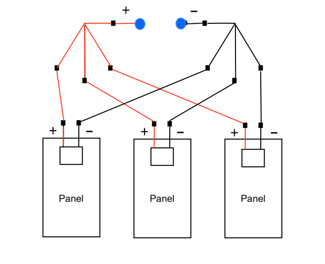
Diagram of RV solar power upgrade from 1 panel to 3 panels in parallel

Our 2 new panels would be wired in parallel with the existing panel, connecting all the positives together on one 3-to-1 branch connector and all the negatives on the other. The extension cables would connect to the wires coming up through the holes in the roof (blue circles). Note that the holes in the roof are actually under the center panel and the 6′ extension cables are drawn super short.

Our mission was to :

  1. Lift the existing solar panel so we could access the cabling underneath
  2. Disconnect the MC4 connectors on the panel’s leads from the MC4 connectors on the cables that come up from the solar charge controller in the rig
  3. Reconnect the cables coming from the charge controller to the new 6′ “extension” cables
  4. Connect the “extension” cables to the legs of the 3-to-1 branch connectors which would designate one as “positive” and one as “negative”
  5. Connect each panel’s positive cable to the “positive” 3-to-1 branch connectors
  6. Connect each panel’s negative cable to the “negative” 3-to-1 branch connectors

All of this would be done by snapping the MC4 connectors together, simply inserting one end into the other and pressing it together. So easy!

There’s a special tool for disconnecting MC4 connectors, but you can also disconnect them with your fingers by keeping the tab on one side depressed as you pull the two pieces apart.

Connecting MC4 connectors in an RV solar panel installation

MC4 connectors snap together.

To get at the cables under the existing Go power solar panel, Mark removed the hardened sealant that was covering each of the mounting brackets. He used a screwdriver but a narrow and rigid putty knife would work too.

Removing a Go Power solar panel from an RV roof

First step was to lift up the existing panel which required removing the sealant on the mounting bracket screws and then unscrewing the screws.

Then he unscrewed each of the screws holding the mounting brackets in place.

We bought a wonderful cordless power screwdriver last year that we BOTH absolutely LOVE! It makes screwing and unscrewing things infinitely easier than doing it by hand, and it’s much less bulky than a cordless drill.

Ryobi cordless screwdriver
Removing a Go Power solar panel from an RV roof

Unscrewing the screws.
The cordless screwdriver is one of our favorite tools!

He unscrewed all four feet and then lifted up one side to get at the cables underneath.

Changing the wiring under a Go Power solar panel under an RV roof

Working under the existing solar panel.

A positive (red) and negative (black) cable came up through the roof from the interior of the rig where they were connected to the solar charge controller and were connected directly to the solar panel. Mark disconnected each cable from the solar panel and then reconnected them to the two 6′ extension cables we had purchased.

Changing the wiring under a solar panel on an RV roof

The positive and negative extension cables go between the 3-to-1 branch connectors and the cables coming up through the roof from the charge controller inside the rig.

Then he connected the extension cables to the “legs” of each of the two 3-to-1 MC4 branch connectors (bird feet) and connected the solar panel’s negative and positve leads to the “toes” of the 3-to-1 branch connectors.
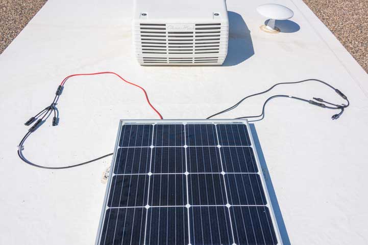
RV solar panel MC4 connector wiring on an RV roof

The original panel (black leads going to the middle “toes”) and the solar charge controller (red and black extension cables going to the “legs”) are now wired into the 3-to-1 branch connectors. We ran into the rig to verify everything looked okay and we saw the float voltage of 13.5 volts on the charge controller display.

Next, we needed to get the two new Renogy solar panels onto the roof of the RV, place them on either side of the existing panel, and then connect their positive and negative leads to the positive and negative 3-to-1 branch connectors.

Before that, though, we needed to figure out how to get the panels up onto the roof which is 13.5 feet in the air! We opened the patio of the toy hauler and put a ladder on it. This was much more secure than carrying a heavy solar panel one handed up the ladder attached to the side of the rig!
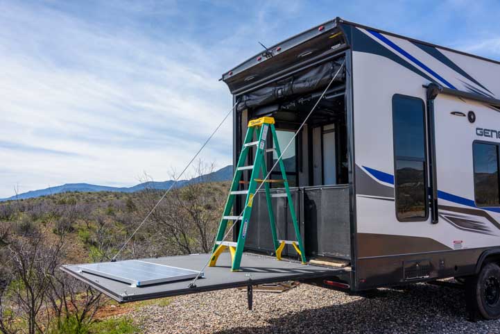
Ladder roof access on a toy hauler RV patio

The most solid way to get the panels up to the roof was to put a ladder on the patio!

Lifting a solar panel onto an RV roof

Here comes the first one!

Once we got both panels up on the roof, we attached the MC4 connectors on the two new panels’ leads to the outer “toes” of the two 3-to-1 branch connectors, positive to positive and negative to negative.

Now all three panels were completely wired up in parallel.

Three solar panels wired with MC4 connectors on an RV roof

.

The next step was to mount the solar panels on the roof.

The roof is just wide enough (it’s an 8.5′ “widebody” trailer) that we could place the three panels side by side, leaving enough space between them so we could walk beyond them to the far end of the rig.

First Mark screwed the original Go Power panel’s mounting brackets back into the roof.

Then we used the Renogy mounting Z brackets to mount the new Renogy solar panels. The Renogy mounting brackets came with very handy hex head self-tapping screws.

Self-tapping screws for installing a Renogy solar panel on an RV roof

Self-tapping screws. So easy!

Then Mark used a scratch awl to make a starter hole for the self-tapping screws. Pounding a nail in a little ways would have worked too.
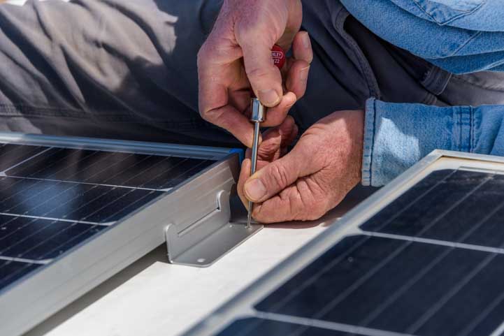
Mounting an RV solar panel on the roof

Mark made a starter hole for the screws with a scratch awl.

Then he used a cordless drill with a hex head bit to screw them in all the way.

RV solar panel installation- attaching the solar panels to the roof

The mounting Z brackets got screwed into the roof.

Solar panel mounting brackets screw directly into the RV roof

Done.

Last of all, he used Dicor Self-Leveling Lap Sealant in a caulk gun to cover all the screws and seal all the edges of the mounting brackets. This will ensure that no water can find its way through the roof!

Sealing the holes in an RV roof after mounting a solar panel

Dicor Self-Leveling Lap Sealant seals the whole mounting bracket so water can’t leak in.

Dicor Lap Sealant on a solar panel mounting bracket

After the Dicor Lap Sealant had leveled out, it completely surrounded and covered the mounting bracket

Ta da! The finished product looked great!

RV solar upgrade cheap and easy with Go Power and Renogy

.

I couldn’t believe how easy this project turned out to be. Of course, the hardest parts were already done for us: running the cables from the roof down into the interior of the rig, wiring up the solar charge controller and wiring up the inverter. All we had to do was add two more panels and wire them up with the handy MC4 connectors.

If you have purchased a rig that has a “starter” solar power system like the Go Power system on our toy hauler, it’s not difficult to upgrade it like we did so you have the maximum amount of solar panel wattage that the charge controller can accept.

One thing to consider before buying any solar gear, especially from an online retailer, is to buy each piece individually rather than in a big kit. The problem with a kit is that if one item in the kit doesn’t work and needs to be returned, online retailers, like Amazon, may require you to return the entire kit. If the failed element is a solar panel and you’ve already installed the other panels in the kit and they are working fine, it may be a hassle to get approval to return just the one broken panel. I’ve read of cases where the entire system had to be dismantled and reboxed and sent back. For that reason, we opted to buy each piece separately just in case.

Subscribe
Never miss a post — it’s free!

Further reading…

SOLAR POWER OVERVIEW and TUTORIAL

BATTERIES and BATTERY CHARGING SYSTEMS

LIVING ON 12 VOLTS

ARTICLES ABOUT OUR GENESIS SUPREME TOY HAULER

REFERENCES

Our most recent posts:

More of our Latest Posts are in the MENU.   New to this site? Visit RVers Start Here to find where we keep all the good stuff. Also check out our COOL NEW GEAR STORE!! *** CLICK HERE *** to see it!

RV Solar Power Made Simple

Thanks to solar power, we have lived completely off the grid in two trailers and a sailboat full-time since May 2007. Without doubt, our solar power installations have given us more independence and freedom as full-time RVers and sailors than anything else in these lifestyles. It has allowed us to go anywhere at anytime, and has revolutionized our lives.

On this page I describe the two systems we have had on our trailers. These were installed in 2007 and 2008 respectively. Prices for solar power equipment have dropped every year since then, however the prices listed throughout this page are from August 2014:

  • A Small (minimal) RV Solar installation for ~$700 that we used full-time for a year of boondocking in 2007
  • A Full-timer (all you need) RV Solar installation for ~$2,500 that we have used for full-time boondocking since 2008

I also offer a little theory and reveal some of the discoveries we have made along the way. For more info, please see our Solar Power Tutorial pages and our Sailboat Solar Power Installation page.

Links to all of our articles about solar power can be found on our Solar Power For RVs and Boats page.

You can navigate to different parts of this article by using these links:

WHY BOTHER WITH A SOLAR POWER INSTALLATION ON AN RV?

Return to top

The biggest advantage of a solar power system in an RV is that the system works from dawn to dusk, silently, odor free and without requiring any fuel or maintenance, no matter where you are or what you are doing. Towing, parked at the grocery store, or camped, the batteries are being charged. They start getting charged before you finish breakfast, keep charging while you hike or go sightseeing, and continue all day, rain or shine. They don’t quit charging until nightfall. You never have to think about the batteries getting charged. It just happens. In our current rig, I feel like we have electrical hookups all the time — and we never get hookups any more!

Traveling full-time since 2007, we have connected to electrical hookups for a total of about 25 days, and that was during our first 18 months on the road. The last time we got electrical hookups was in October, 2008. Since we began our full-time travels in 2007, as of June 2019, we have boondocked in our RV nearly 3,200 nights. We also lived on solar power on our sailboat for over 900 nights during our sailing cruise of Mexico.

We do carry a Yamaha 2400i generator, but use it only a few days each year, either after a long period of winter storms to give the batteries a boost, or on hot summer days to run our 15,000 BTU air conditioner. We have used it a total of about 20 times since we purchased it in December 2007. We run it every six months or so to flush the gas through the lines. Little as we have used it, we have found the Yamaha to be a fabulous generator. It has always started on the first pull, even after it sat in storage for 20 months when we first moved onto our sailboat!

Our first solar power installation that we used for a year in 2007 was a “small” system that allowed us to use almost every appliance we owned, that is, laptop, TV, hair dryer, vacuum, two-way radio charger, power drill, etc. However, we had to be very conservative with our electrical use during the winter months. A similar “small” RV solar power kit can be found here.

Our second “full-timer” solar power system that we have been using since 2008 is like having full electrical hookups wherever we go. Very little conservation is necessary! On our biggest electrical use day to date, we watched our 26″ LCD TV with its huge surround-sound system and sub-woofer for 15 hours (it was the Olympics!) and ran two 13″ laptops for 7 hours, made popcorn in the microwave and ran several lights for 4 hours in the evening. It was July, and the next day was very sunny and the batteries were fully charged by mid-afternoon. A similar “full-time” RV solar power kit can be found here.

Here are some sample kits, smaller and bigger in size, and their prices. The only trouble with buying a component kit is that if one component fails the whole kit has to be returned. The third item, however, is a portable suitcase kit that does make a lot of sense for someone who doesn’t want to hassle with the installation just yet (you can always sell the portable kit later).

BASIC ELEMENTS OF A SOLAR POWER INSTALLATION

Return to top

BATTERY CHARGING and AC POWER
The basic components of all solar power installations is the same, and is comprised of two major subsystems: BATTERY CHARGING to get the batteries charged up and AC (120v) POWER for appliances that can’t be run on DC (12v) power (i.e., TV, computer, vacuum, hair dryer, etc.).

The BATTERY CHARGING subsystem includes these components:

  • Batteries
  • Solar panel(s)
  • Charge controller to protect the batteries from getting overcharged

The AC POWER subsystem includes this component:

  • Inverter(s) to convert the batteries’ 12 volt DC power to 120v AC power

GET YOUR HANDS DIRTY!

300 watt inverter for an RV solar panel installation

A 350 watt portable inverter
Plug it into a cigarette lighter

It is hard to “play with” the battery charging subsystem of a solar power installation to get a feel for how it works until you actually take the leap and buy a solar panel, charge controller and cables and hook it all up to the batteries. One great option if you don’t want to do any wiring but want some hands on experience is to get a portable solar panel kit. You can sell it later if you want to upgrade to a rooftop system.

You can get the hang of how the AC power subsystem works very easily. Simply run down to Walmart or any auto parts store and pick up a $15-$20 inverter that plugs into a cigarette lighter DC outlet. Plug it into the lighter in your car, turn it on, and then plug your laptop into it or your electric razor or any other small appliance. Now your 12 volt car battery is operating your 120 volt appliance.

Big inverters that can run the microwave, toaster, blender and vacuum cleaner work on exactly the same principal, the difference is just the amount of power the inverter can produce. Big inverters are also wired directly to the batteries rather than plugging into a cigarette lighter.

IS SOLAR POWER EXPENSIVE? SMALL SYSTEMS VERSUS BIG SYSTEMS

The difference between the “small” system we used for one year on our little Lynx travel trailer and our “full-timer” system we have now on our big Hitchhiker fifth wheel is simply the overall capacity of each of the components. That is, the capacity of the battery charging system (solar panels, batteries and charge controller) and of the AC power system (the inverter).

In functional terms this means that the difference between the “small” and “full-timer” systems is threefold:

1) the ability to run more appliances at once (i.e., have two laptops running while the TV and blender are going)
2) the ability to run larger appliances (i.e., using a VitaMix versus a small blender)
3) the ability to run more appliances for a longer time at night without discharging the batteries too much.

So, in a nutshell, the two subsystems — battery charging (batteries + panels + charge controller) and AC power (inverter(s)) — combine to do the same job as plugging a generator into the shore power connector on the side of the rig. The panels and charge controller charge the batteries. The inverter makes it possible to use AC appliances.

The cost of the parts for these installations is:

Small: $700 – Comparable to having a Yamaha 1000i generator
Full-timer: $2,500 – Comparable to having a built-in Cummins Onan 2.5KW generator

With solar power there is no noise, no fuel cost, no maintenance and no smell, unlike a generator. However, it is not possible to run the air conditioning in the summertime on solar power, unless you have a massive system with several hundred pounds of batteries and a roof absolutely loaded with panels. As mentioned before, we use our Yamaha 2400i generator to run our 15,000 BTU air conditioner.


OUR “SMALL” RV SOLAR POWER SYSTEM (~$700 in parts)

Return to top

This setup is a fully functional, inexpensive solar power installation, and is what we used for a 350 nights in our first year in our Lynx travel trailer. It could power a 19″ LCD TV and DVD player, radio, laptop and vacuum as well as charge camera batteries, razor, toothbrush, cordless drill, cell phone, etc.

  • Two 6-volt batteries (wired in series) giving 220 amp-hours of capacity $250

    Ours were Energizers from Sam’s Club

  • 140 watts of solar power $175

    Ours was a Kyocera 130 watt DC panel. Today Kyocera sells the 140 watt panel instead.

  • A charge controller that can support at least 10 amps $90

    Ours was a Morningstar Sunsaver 10 amp charge controller (consider a Sunsaver 20)

  • A portable inverter that can supply 1000 watts of AC power $80

    Ours was a Pro One 800 watt inverter

  • Cables, connectors and mounting brackets $100

Here are the parts for the system (except for batteries and cables) — solar panel, solar charge controller and inverter:

This system is the smallest size system I would consider for an RV if you want to drycamp or boondock for more than a night or two and be comfortable. This setup worked great in the spring, summer and fall when the sun was high in the sky and the days were long. We never thought too much about our power use until the wintertime when the days got short and the nights got long and cold. Then we began to wish for a bigger system.

RV solar panel installation - wiring the panel's junction box

Mark installs our first solar panel on the roof.
He chose a nice spot by the ocean to do it!

On those long cold winter nights we had to conserve our use of lights and the TV to make sure our furnace (which used a lot of battery power) could still run. We used oil lamps a lot in the evenings. If we had stayed in that trailer longer, we would have installed a vent-free propane heater that did not use any battery power (we eventually did that in our bigger trailer the following winter: see our Vent-Free Propane Heater Installation page).

I think every RV should have this kind of a charging system installed as standard equipment, as it is useful even for the most short-term camping, like weekends and week-long vacations during the summer months.

When we installed this “small” system in our little Lynx trailer in June 2007, we were quoted $135-$350 for installation. Mark is very handy (although he is not a Master Electrician), and he found the installation was not difficult at all and completed it in one day.

SOME THEORY – SIZING THE SYSTEM

Return to top

CHARGING & CONSUMPTION

Here is some theory to explain why the above system is “sufficient” but is not great for “full-time” use. When it comes to a solar battery charging system, the concept of power charging and consumption is very simple. The amount of power you can use, or take out of the batteries, is essentially only as much as the amount you can put into the batteries. If you use (or take out) more power than you replace (or charge them with), sooner or later your batteries will be discharged and dead. The batteries are just a temporary storage place for electricity. They act as a flow-through area for the power you are going to use.

The most important part of any solar setup is the amount of charging going on (i.e., the total size, or capacity, of the solar panels), and you want that to be greater than the amount of electricity you use. More must go into the batteries than comes out. You can have an infinite number of batteries and eventually discharge them all completely if you repeatedly use more electricity than your solar panels put in.

We often find people want to add batteries to address their power shortages when what they really need to do is add more solar panels. As a rule of thumb, don’t use more than 1/3 to 1/2 of the total capacity of the batteries in one night. More important, though, is that the bigger the solar power panel array, the better. And lastly, Keep the size and age of all the batteries in the system fairly similar so the strong ones don’t waste their energy helping the weak ones keep up.

AMPS and AMP-HOURS

Appliances use amps to run. Another unit, the amp-hour (abbreviated as “Ah“), refers to the number of amps an appliance uses when it is run for an hour. For instance, an appliance that uses three amps to run will use up three amp-hours when it runs for an hour. These amp-hours will be drawn from the batteries, and the batteries, in turn, will look to the solar panels to recharge the amp-hours they have forked over to the appliance. It is for this reason that you need to know how many amp-hours you will use in a typical day. Ultimately those amp-hours must be replaced by the solar panels, so the size and number of panels you purchase will be determined by how many amp-hours you use in a day.

To estimate how many amp-hours you might use in a day, estimate how many hours each appliance will run and multiply that by the number of amps the appliance uses. We have measured some of the appliances in our trailer, and this is how many amps they use:

Single bulb DC light — 1.5 amps
Dual bulb DC light — 3.0 amps
Dual bulb fluorescent light — 1.5 amps
19″ LCD TV — 5.5 amps
DVD / CD Player — 0.5 amps
13″ MacBook laptop, on & running — 6-8 amps
13″ MacBook, off and charging — 1.6 amps
Sonicare toothbrush charging — 0.1 amps
FM Radio w/ surround-sound — 3.0 amps
12′ string of rope lights — 3.3 amps

We find that we typically use anywhere from 50 to 150 amp-hours per day, most commonly in the 70-90 range.

HOW MANY AMP-HOURS DOES MY FAVORITE GIZMO USE?

Since RV solar power systems are DC battery based, it is helpful to know how many amps (in DC) various appliances use. Multiplying that value by the number of hours the appliance is used each day then reveals how many amp-hours the appliance will require from the battery in the course of a day.

Most DC appliances list their amp usage in the user manual or spec sheet. In contrast, most AC appliances list their wattage in the user manual instead of amperage. So, for AC appliances that are run on an inverter you have to do some math to get their equivalent DC amperage rating.

You can get a rough estimate of the number of amps that an AC device will use on an inverter simply by dividing the wattage by 10.

Why is that?

Here’s one way to look at it: Technically, Watts = Volts x Amps. AC circuits run at ~120 volts. DC circuits run at 12 volts. An AC appliance will use the same number of watts whether running on a DC or AC. On a DC circuit (using an inverter so it can run), that AC appliance will use 10 times as many amps as it will on an AC circuit (that is, 120/12 = 10).

Here’s another way to look at it: Watts / Volts = Amps. So, to determine most precisely how many DC amps an AC appliance will use when running on an inverter, start by dividing the number of watts it uses by 12 volts to get its Amps DC. HOWEVER, keep in mind that inverters are not 100% efficient. Typically they are only about 85% efficient. That is, an inverter loses a bunch of watts to heat as it runs — about 15% of the watts it needs to run get dissipated into heat. So, it takes more watts to get the required amps out of the inverter, the exact figure being 1 / 85%. This means that after you divide the appliance’s Watts by its Volts (Watts / 12, as I mentioned above), then you have to divide that result by 0.85. This is messy.

Rather than dividing watts first by 12 and then again by 0.85, you can simply divide the watts by 10 and get a pretty close estimate. (That is, (1/12)/0.85 = 0.1)

Our AC 19″ LCD TV is rated at 65 watts. How many amps is that DC? 65/10 = 6.5 amps DC. We measured the TV at the volume we like to hear it and it was using 5.5 amps. If we cranked up the volume, the meter went up to 6.5 amps.

Likewise, our old white MacBook Pro laptop was rated for 65 watts. As we opened and closed files and started and stopped various programs, the meter zoomed all over the place between 3 amps and 8 amps. When we ran Adobe Lightroom, which is very disk and memory intensive, the readings hovered in the 7-8 amp range. So on average you could say it uses about 6.5 amps DC.

When we shut down the laptop and left it plugged in and charging, the meter dropped to 1.6 amps. This is important if you are trying to conserve electricity! Run your laptop on its own battery until the battery is depleted. Then turn it off and let it charge from the inverter while you do something else!

HOW DO YOU MEASURE THE POWER USAGE OF A DEVICE?

If you have nothing running in the rig (no computers running, no TV, no vacuum or toaster, etc.), you can measure the current a device is drawing from the batteries using a clamp-on meter around one of the battery cables. To measure the AC current of a small device, you can use a Kill-a-Watt meter. Simply plug it into an AC outlet and plug your device into it.

WHERE DO THE BATTERIES FIT IN?

Battery storage capacity is measured in amp-hours (Ah), and more is better. As a starting point, most new RVs come equipped with one 12-volt Group 24 battery which will give you about 70-85 Ah of capacity. Assuming the sun has charged the batteries completely by nightfall, and sticking to the rule of using only 1/3 of your total battery capacity each night, you will have only 25 Ah available each evening. That isn’t very much!

What is the best upgrade strategy?

Upgrading to two 12-volt Group 24 batteries (wired in parallel) will give you 140-170 Ah of capacity.

However, a 6-volt golf cart style battery has the same footprint as a Group 24 12-volt battery (although it is about 3″ taller), and a pair of them wired in series will give you about 210-240 Ah of capacity.

So, rather than buying a second 12-volt Group 24 batteries and getting just 140-170 Ah of capacity out of the pair, why not sell the 12 volt battery and buy to two 6-volt golf cart style batteries for 210-240 Ah of capacity? That’s what we did on our first trailer. Just make sure that you have enough height in the battery compartment for the taller golf cart batteries.

WHAT ABOUT BATTERY MAINTENANCE?

So far I’ve been talking about wet cell batteries, and these kinds of batteries need to be maintained. Wet cell batteries are made with thick metal plates and liquid between them. Over time the liquid evaporates and needs to be replaced with distilled water. Also, over time, sulphite builds up on the plates and needs to be removed by “equalizing” the batteries.

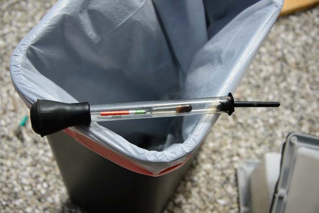
Hydrometer Reading on Battery

Use a hydrometer to check each battery cell.

Before we upgraded to AGM batteries, Once a month Mark would check the liquid levels in each cell of each battery and pours in a little distilled water wherever needed. He also checked the condition of each battery cell using a hydrometer. This little device indicates whether a cell is functioning at full capacity. Then he equalizes the batteries by programming our charge controller to raise the voltage on them to one volt higher than their normal charging voltage for five hours. Last of all, he re-checks the liquid level in each battery cell and adds distilled water as needed and re-checks each cell with the hydrometer. Usually any cells that had a poor reading before equalizing now give a good reading.

This maintenance stuff can be avoided by buying AGM batteries which are maintenance free. However, AGM batteries are really expensive. One big advantage of AGM batteries for sailors and for people with tight battery compartments is that they operate fine in any position, that is, they can be installed on their sides and will operate when a sailboat is heeling. We had them on our sailboat.

On our trailers, we initially opted for wet cell batteries. We had Trojan 105 wet cell batteries for the first five years on our fifth wheel. Then we replaced them with cheaper Costco batteries from Interstate (Johnson Controls).

The Trojans worked very well, but replacing them with cheapo batteries was a mistake. The cheap batteries failed completely within 14 months.

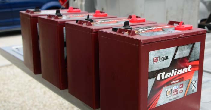
We now have four Trojan T-105 Reliant AGM batteries which are truly awesome. They are a little more money than the T-105 wet cell batteries, but they are superior and, in our minds, worth the extra little bit of cash.

For price comparisons: Trojan Reliant AGM (single), VMaxTanks AGM (set of 4 & free shipping), Trojan T105 Wet Cell (single):

To learn more about our new batteries, why we chose them, and how we upgraded the power plant on our trailer in April 2015, visit:

Wet Cell vs. AGM Batteries – Why We Upgraded to AGM Batteries PLUS Wiring Tips!
RV Electrical System Overhaul

To learn more about batteries and what “single-stage” and “multi-stage” battery charging is all about, visit:

RV and Marine Battery Charging Basics

AND HOW ABOUT THE SOLAR PANELS?

Battery capacity is only part of the story. The ultimate limiting factor is how many amp-hours the solar panels can put into the batteries during the day. If the solar panels are sized too small to charge the batteries sufficiently each day, you will eventually discharge the batteries over a series of days and they will be dead.

Solar panels are rated in terms of Watts. The relationship between the amp-hours that the panel can store in a battery and the panel’s watts rating is not straight forward. Suffice it to say that a 130 Watt panel produces 7.5 amps in maximum sunlight when the panel is exactly perpendicular to the sun, and both of those numbers are available in the specs for the panel. What isn’t stated, however, is how many amp-hours a panel will produce in a given day. That is because it varies by what latitude you are at, what angle the sun is to the panel (which changes all day long), how brightly the sun shines, how many clouds go by, etc.

We have found that each of our 120 watt and 130 watt panels typically produces between about 8 Ah and 40 Ah per day depending on the season, weather, latitude, battery demands, etc. Most commonly, they produce around 25-30 Ah per day each.

If you have the time and inclination (who’s got that stuff?), you can figure out how many amp-hours you use each night. Make sure that that number is less than 1/3 of your total battery capacity AND make sure your panels can provide that many amp-hours of charging each day.

But all that sounds very difficult.

Solar panels also come in a variety of flavors, including rigid or flexible and monocrystalline or polycrystalline as seen below:

To learn more about SOLAR PANELS, see our detailed review of the pros and cons of the different types of panels available today:

Solar Panel Selection – Flexible or Rigid? 12 volt or 24 volt? Monocrystalline or Polycrystalline?

NEVERMIND THE THEORY – JUST TELL ME WHAT SIZE STUFF I NEED!

As I have mentioned before, we changed how we lived when we had a small solar power installation and again when we got a big one. You can opt to live with very little electricity or not.

We met a couple living on their 27′ sailboat on its trailer in the desert in Quartzsite, Arizona (they were on their way to launch it in the Sea of Cortez). They were using just 6 amp-hours per day because they had a tiny solar panel. Lord knows, I never saw their lights on at night!

In our little Lynx travel trailer we used about 25-35 amp-hours per day. We relied on kerosene lamps for much of our lighting at night in the winter.

In our Hitchhiker fifth wheel we use an average of 60-120 amp-hours per day and we do not conserve electricity.

So as a rule of thumb, here is the number of amp-hours you might consume per day:

• 6 Ah = living ultra-conservatively
• 35 Ah = living very modestly
• 120 Ah = living much the way you do in your house

The amp-hour capacity of your battery bank should be three (to four) times your typical daily amp-hour usage.

A popular rule of thumb is to match (roughly) the amp-hour capacity of the batteries to the watts capacity of the solar panels. So, 140 Ah of battery capacity “goes with” 140 watts of solar power. 440 Ah of batteries “goes with” 440 watts of solar power.

However, having more solar capacity than that is not a problem, as it gives you much more flexibility in case you have cloudy days, the panels aren’t oriented well towards the sun, or you have periodic shading during the day from buildings or trees.

Side note: The average American house uses about 30 kilowatt-hours (kWh) of electricity per day (see here), whereas we use anywhere from 0.6 to 1.2 kWh per day in our RV. This is because houses are much bigger and more complex and have much larger appliances and systems that run on electricity (refrigerator(s), stove/oven, hot water heater, heat and air conditioning, etc.).

It is also interesting to note that the ~1 kWh of power that our fifth wheel requires to recharge its batteries every day is approximately the same amount of energy that is required to recharge the batteries of a Tesla Model S after it is driven three miles (see here). Charging a frequently driven Tesla’s batteries exclusively with solar power would require an immense solar panel array.


OUR “FULL-TIMER” RV SOLAR POWER SYSTEM (~$2,500 in parts)

Return to top

Fifth wheel trailer solar power 681

In a nutshell, in order to run your RV with the same level of comfort as a house, using all of your appliances whenever you feel like it without thinking about conserving at all, you will need at least the following:

  • Four or more 6-volt batteries giving you at least 440 amp-hours of capacity

    We have four 6-volt batteries (2 pairs of batteries in series to make two 12-volt equivalent batteries, and then those 2 twelve volt equivalent batteries placed in parallel with each other). We had Trojan 105’s for the first five years, and after that we’ve had batteries from Costco, ~$480, which we soon replaced with Trojan T-105 AGM Reliant batteries, $1,200 (see note below).

  • 500 or more watts of solar power (preferably 600-800 watts)

    We have three 120-watt Mitsubishi panels and one 130-watt Kyocera panel, for a total of 490 watts of solar power, `$1,140

  • A charge controller that can support 40 amps or more (preferably 60 or 80 amps)

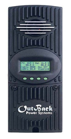
    We have an Outback FlexMax 60 60 amp charge controller (consider the FlexMax 80) $565
    For more info see our page: Solar Charge Controllers – Optimizing RV Battery Charging

  • A true sine wave inverter that can supply at least 1000 watts of AC power (preferably 2000 or 3000 watts)

    For 7 years we had an Exceltech XP 1100 watt true sine wave inverter $600.

PLEASE NOTE: In April, 2015, we upgraded to Trojan 105 Reliant AGM batteries ($1,200) and an Exeltech XP 2000 watt true sine wave inverter ($1,700). See our post RV Electrical Power System Overhaul to learn more.

This system will power everything except the air conditioner, regardless of weather or season. My notes indicating “preferably” larger sizes for everything reflects the fact that our installation is now quite old and component parts costs are half what they were when we were buying. More is definitely better.

I’ve never heard anyone say they wished they had less solar power!

Mark did the installation of this solar power system on our Hitchhiker fifth wheel. My rough guess is that the installation might have cost $700-$1,500 if done by an experienced installer. It took him three partial days, largely because we were boondocked in the woods about 15 miles from Home Depot, and I had to keep running back and forth to get little things for him!

NOTES and LESSONS LEARNED

Return to top

More and more solar power equipment manufacturers are selling complete kits for RVs, boats and cabins. Here is an example full-timer kit from Go Power, and a slightly smaller full-timer system from Renogy. Here is a small solar power kit from Go Power for “weekender/vacation” use and another small solar kit using Renogy panels.

Also, if you don’t want the hassle of doing an installation, here’s a nifty portable solar panel kit that folds into an easy-to-carry suitcase!!


INVERTER and CONVERTER CONFUSION

If you are like me, the terms “inverter” and “converter” are confusing. They sound so similar it seems they must be one and the same thing. They are actually two very different components with very different missions in an RV.

CONVERTERS

A converter takes the AC power coming in from the shore power cord (via electrical hookups or a generator) and gives power to all the DC appliances in the rig so the batteries can take a break. It essentially does what the batteries do, but does it only when there is shore power.

The DC converter in an RV also charges the batteries while connected to shore power. Some converters have sophisticated multi-stage charging mechanisms, and others simply provide a trickle charge.

For more about single-stage versus multi-stage charging, click here.

The DC converter is not involved in the solar power system. In our “full-time” solar setup, the DC converter is actually unplugged because our inverter powers all the AC outlets in the rig. Because of our converter’s design, when it is plugged in it senses when there is AC power available and automatically turns on. This would impose a huge demand on our batteries whenever we turned on the inverter.

Once in a while, when the skies have been overcast or stormy for a few days, we fire up our trusty Yamaha 2400i generator to bring the batteries up to full charge. We plug our shore power cord into the generator, unplug the inverter and plug in the converter. Now the converter is charging the batteries.

The converter that came with our rig was a single-stage trickle charge Atwood 55 amp converter. This was very inefficient for use with the generator because it charges at such a slow rate that we had to run the generator for hours and hours to get the batteries charged up.

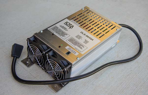
In April, 2015, we replaced that converter with a slick new Iota DLS-90 / IQ4 converter. This converter can put as much as 90 amps into the batteries and has a true multi-stage charging algorithm. To see our introductory post about our big electrical system upgrade, see this post: RV Electrical Power System Overhaul

For more about converters, visit: RV Converters, Inverter/Chargers & Engine Alternator Battery Charging Systems

Almost all trailers and many smaller motorhomes have a converter installed at the factory.

INVERTERS

An inverter takes the DC power from the batteries and converts it to AC power so you can run things like TVs, computers, vacuum cleaners, hair dryers, toasters, etc., and also charge things like your phone and camera batteries. Turn on the inverter, plug an AC appliance like an electric razor or TV into it, and poof, the razor or TV works.

Inverters come in two flavors:

True Sine Wave (or Pure Sine Wave) which means the AC power signal coming out of the inverter is identical to the power signal of a wall outlet in a house (a smooth sine wave).

Modified Sine Wave which means the waveform is clipped at the top and bottom and is stair-stepped in between rather than being a smooth sine wave.

It is easier to convert DC power to a square-type wave than a smooth sine wave, so modified sine wave inverters are much cheaper. However, some sensitive AC appliances don’t work with a modified sine wave inverter.

We purchased a high-end true sine wave inverter for our “full-time” solar setup, because it matched the quality of the system and our particular unit was noted for its ruggedness (we run it 15 hours a day, sometimes 24). Our Exeltech true sine-wave inverter is designed to operate medical equipment, so it provides exceptionally clean and stable AC power.

See our story “How Much Inverter Is Enough?” to learn about what happened to us when we accidentally “blew up” our fancy Exeltech true sine wave inverter and had to live on a tiny cheapo 350 watt modified sine wave inverter while waiting for the parts to fix it!

Ironically, some RV parks have unstable AC power that can damage AC appliances in an RV. Our inverter power from our Exeltech is cleaner and more reliable (Exeltech inverters are designed to power sensitive medical equipment)! Desktop computers, laser printers, TV and stereo equipment and Sonicare toothbrushes are the most likely appliances to have trouble with modified sine wave inverters. However, when we used modified sine wave inverters exclusively with our small solar power setup on our Lynx travel trailer, we never had a problem with any of our appliances. Modified sine wave inverters often have loud fans, and Mark did have to put some WD40 on our Radio Shack inverter twice when the fan quit working unexpectedly.

INVERTER/CHARGERS

To add to the confusion about inverters and converters, some inverters combine a little of the functionality of both an inverter and a converter. These are called inverter/chargers and have two independent functions: (1) convert the batteries’ DC power to AC (inverter), and (2) use the AC power from the shore power cord (connected to electrical hookups or generator) and charge the batteries.

These are pricey pieces of equipment and many higher end motorhomes come with them. Our sailboat came with both a 600 watt pure sine wave inverter (which we used for everything on the boat except the microwave) and a 2500 watt modified sine wave inverter/charger (which powered the microwave and charged the batteries when we plugged into shore power).

NOW THAT IT’S ALL CLEAR, THE MANUFACTURERS MESS US UP!

The distinction between inverters and converters is pretty easy, isn’t it? However, recently when I was in an auto parts store I noticed a box labeled “POWER CONVERTER” and the picture and description were very clearly that of an INVERTER! So, maybe the distinction is going to get all muddied up after all.

For more about inverter/chargers, visit: RV Converters, Inverter/Chargers & Engine Alternator Battery Charging Systems

AN IMPORTANT NOTE ON RV REFRIGERATORS

Return to top

Because conventional propane RV refrigerators are inefficient and are (shockingly) expected to fail within ten years of service (see our blog post about that here), the current trend in full-time RVs is to manufacture them with residential AC refrigerators. These RVs are built with an inverter large enough to power the refrigerator while the RV is in transit. This is great for folks that are going to plug into electrical hookups 100% of the time. However, the electricity required to run a refrigerator, whether AC or DC, and no matter how Energy Star Efficient it is rated to be, is astronomical.

A typical 10 to 12 cubic foot Energy Star refrigerator will use over 300 kilowatts per year, or 822 watts per day. There is some energy lost when running on an inverter, so this will be roughly 822 Watts / 10 Volts = 82 amp-hours per day. To keep this fridge operating during the short days of winter when the sun is low in the sky, you will need 400+ watts of solar panels and 200+ amp-hours of battery capacity in addition to whatever you will need to run the rest of the household.

If you plan to boondock a lot, and you don’t want to run your generator 24/7, be prepared to outfit your rig with over 1,000 watts of solar panels and close to 1,000 amp-hours of battery capacity to power a residential refrigerator.

Non-Energy Star compliant DC electric refrigerators are even worse. Our sailboat had a 3.5 cubic foot DC refrigerator (“counter height” or “dorm size”) that was built for RV use. It did not have a freezer compartment. We had 710 amp-hours of AGM batteries and 555 watts of solar power. Granted, we were living in the tropics and the ambient cabin temperature was generally 85 degrees. The refrigerator compressor ran about 50% of the time and our solar power system was pushed to the max to keep the batteries topped off every day.

We had a separate standalone 2.5 cubic foot DC freezer on our sailboat. If we turned the freezer on, the solar panels could not keep the batteries charged without supplemental charging from the engine alternator every third or fourth day.

Residential refrigerators have vastly improved in recent years, running on a mere 25% of the electricity they used to use in 1986, and they are only getting better. For more information about refrigerator energy use and energy saving tips, see this resource: How Much Electricity Does My Refrigerator Use?

I have corresponded at length with a reader who has been boondocking 95% of the time for 6 months in a 40′ Tiffin Phaeton motorhome. He has a Whirlpool 22 cubic foot residential refrigerator, 1,140 watts of solar panels on his roof and 940 amp-hours of battery capacity in his basement. His fridge is powered with a dedicated Xantrex pure sine wave 2,000 watt inverter that is wired through a transfer switch to both his shorepower line and his generator, just in case the inverter fails (he had a 1,500 watt modified sine wave inverter that literally burnt up and started smoking).

So it can be done, but it will be easier in a motorhome that has a big payload capacity than in a fifth wheel or travel trailer that has a smaller payload capacity due to the weight of the batteries required. Even though we had to replace our RV refrigerator in its 8th year of service, we do not want double our battery bank and solar panel array just to power a residential fridge. I would rather put that extra 275 lbs into other things we need in our mobile lifestyle.

PHEW! THAT WAS A LOT OF INFO. WHAT NOW?

Still confused about the components and operation of an RV solar power system? See our four part RV SOLAR POWER TUTORIAL series where these concepts are re-introduced and discussed in greater detail:

Learn more about the different kinds of solar panels on the market:

Solar Panel Selection – Flexible vs. Rigid, 12 volt vs. 24 volt, Monocrystalline vs. Polycrystalline – PLUS Wiring Tips!!

Get the quick-and-dirty shopping list of things to buy for your solar power installation:

Three RV Solar Power Solutions: Small, Portable, and Big!

Want to learn more about BATTERIES and understand how battery charging works at a deeper level? Our Intro to Battery Types and our four-part tutorial series covers all the details involved in charging RV and marine batteries and takes a close look at a variety of specific charging systems, from converters to inverter/chargers to engine alternators to solar charge controllers. It also reveals how these systems work together:

Curious about the solar power installation we did on our sailboat? See our page: SAILBOAT SOLAR POWER INSTALLATION.

In April, 2015, we overhauled our electrical power plant on our trailer. See the introductory post about this upgrade here:
RV ELECTRIC POWER SYSTEM OVERHAUL

Subscribe
Never miss a post — it’s free!

Where do you buy solar panels, charge controllers, inverters and such? Surprisingly, Amazon offers solar power kits and more. Click the following links for a wider selection of:

If you click through to Amazon from anywhere on this website, anything you put in your shopping cart or wish list immediately after that results in a small commission to us at no cost to you, no matter what you search for and no matter when you finalize the purchase. This is a wonderful way that you can "help us help you" with detailed and carefully researched articles. Thank you!


We offer all the information on our website free of charge in hopes of helping help our fellow RVers and cruisers. We have been alarmed and saddened to find portions of the copyrighted material on this page plagiarized in ebooks that are sold for profit, but so it goes. Imitation is the sincerest form of flattery. Good luck with your solar power installation — we hope our articles on this website are useful to you!

Below are some of our most POPULAR POSTS (also in the MENUS above)

Buddy - A Journey in Spirit - The story of an event that changed our lives forever.

ARTICLE INDEXES
  • RV Tech Tips Articles - A one page index of links to all our RV Tech Tips, RV Upgrades & RV Maintenance articles.
  • RV Lifestyle Tip Articles - An index of links to all our RV Lifestyle Tips (finances, boondocking, major repairs, work/jobs, etc.)
  • Solar Power Articles - Overview and tutorial articles for how to design and install solar power on an RV or boat
  • Product Reviews - An index of links to all of our Product Reviews
RV UPGRADES, SYSTEMS & TIPS MONEY FULL-TIME RV LIFESTYLE GEAR STORE
  • Gear Store - A list of the goodies, equipment and gear we've found useful in our RV lifestyle!
 

Our most recent posts:

More of our Latest Posts are in the MENU.   New to this site? Visit RVers Start Here to find where we keep all the good stuff. Also check out our COOL NEW GEAR STORE!! *** CLICK HERE *** to see it!

RV Solar Panels – Flexible or Rigid? 12 or 24 volt? Mono or Poly? Yikes!

There are a lot of decisions to make when you install solar panels on an RV or boat. Some of the most basic are: what size solar panels to buy, whether to go with flexible solar panels or aluminum framed rigid panels, whether the solar cells should be monocrystalline or polycrystalline, and whether to install nominal 12 volt or 24 volt panels.

We have done several RV and marine solar panel installations, and we have used not only 12 volt and 24 volt panels of various sizes but we have also used both aluminum framed rigid solar panels and the newer semi-flexible solar panels. We have also worked with both monocrystalline and polycrystalline solar panels. This article outlines the pros and cons of the various types and sizes of solar panels and offers some things to think about when you are deciding which solar panels to buy for your RV or boat.

RV solar panel selection

.

Our article RV Solar Power Made Simple explains how to determine the overall wattage for an RV solar power installation. In general, a weekend / vacation RV can get by with 200 watts or less while a full-time solar power system is best with 500 watts or more.

SOLAR PANEL SIZE and PLACEMENT

Once you decide on overall capacity for your solar panel array, the next thing to think about is solar panel placement and wiring. The panels should be a matched set of identical or nearly identical panels. If you have a lot of real estate on the RV roof, then you can get a few big panels. If you have a truck camper or your RV roof is cluttered with a lot of things on it already (hatches, vents, antennas, etc.), then you may need to go with smaller panels that can be squeezed in and around everything else.

Solar panel installation on a ffith wheel RV

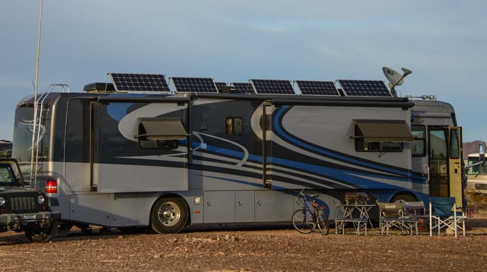
Our fifth wheel trailer is powered by four 120 & 130 watt 12 volt rigid polycrystalline solar panels wired in series

WHAT VOLTAGE IS THAT SOLAR PANEL?

Solar panels are constructed internally with DC wiring, and they are sized to work on 12 or 24 volt circuits. So, they are commonly referred to as 12 or 24 volt solar panels. What’s confusing is that while the nominal voltage of a solar panel may be 12 or 24 volts, the open circuit voltage is higher. So, for a nominal 12 volt solar panel that is 100 watts, the open circuit voltage (“Voc“) will be 17 or 18 volts. Likewise, for a nominal 24 volt panel, the Voc will be 34 to 36 volts.

Also, smaller solar panels (both physically and in terms of watts) are typically nominal 12 volt panels while larger panels are typically 24 volts. Solar panels under about 150 watts in size are usually 12 volt panels. Solar panels over about 150 watts are usually 24 volt panels.

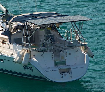
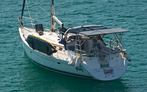
Solar panel installation on a sailboat

For nearly four years, we sailed our boat on Mexico’s coast relying on three 185 watt 24 volt
polycrystalline rigid solar panels, wired in parallel, for all our electrical needs.

Solar panels work best when they are a matched set. The electrical characteristics of all the solar panels in the array need to be very similar, preferably identical. When upgrading a solar power array this can make things complicated as you try to mix and match old small panels with new big ones.

One technique for upgrading is to wire two 12 volt solar panels in series to work on a 24 volt circuit. For instance, if you have two 100 watt 12 volt panels and you are buying a 200 watt 24 volt panel, you can wire the two 100 watt panels in series and then wire that pair in parallel with the new 200 watt solar panel.

This will work as long as the electrical characteristics of the pair of solar panels in series match the electrical characteristics of the single panel that is wired in parallel with them.

THE EFFECT OF SHADE ON SOLAR PANELS

Shade is the biggest enemy of any solar power installation. Unbelievable as it seems, a tiny bit of shade will effectively shut down a solar panel. The impact is dramatic: a few square inches of shade can drop a solar panels current production down from 8 amps to 2 amps. A few more square inches of shade can drop the current production to 0.

Before deciding on the size of the panels, it is worthwhile to take some time to study the various things that might cast shade across them once they are in place. A closed hatch may cause little shade, but when it is open on a hot day, depending on where the sun is in the sky, it might cast a big shadow across a nearby solar panel. Satellite dishes, air conditioners and even holding tank vents can cast sizable shadows as well.

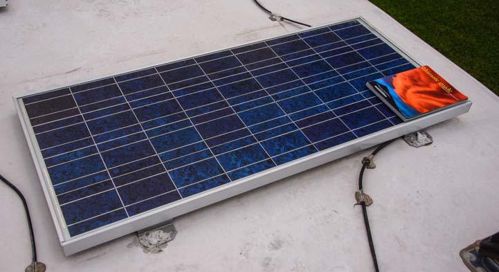
We put a book in one corner of a 120 watt 12 volt panel and discovered that even though it was a small percentage of the surface area of the panel, that 8.5″ x 11″ book was enough to knock down the current production of a 120 watt solar panel by 80%. Rather than producing 7 amps, it produced a measly 1.4 amps. Egads!

Shade on one corner of solar panel

Just 8.5″ x 11″ of shade from this book reduced current production by 80%!

Similarly, shade wreaked havoc on our three185 watt 24 volt panels on our sailboat. The shade from our mast traveled across the panels as the boat swung at anchor, and the current production dropped by 1/3 and then by 2/3 as the shade first crossed one of the three panels and then straddled two of them. It did this over and over, with the current rising and falling repeatedly, as the boat slowly swung back and forth at anchor.

Effect of shade on solar panels installed on sailboat

A line of shade from the mast on our sailboat reduced our solar panel array to 65% and then 35% of its capacity as it traveled across the panels and occasionally straddled two of them.

Shade is a huge concern in the solar power industry, and there are several white papers (here’e one) about the impact of shade on commercial solar panel installations. The gist is the importance of spacing the rows of commercial solar panel arrays in such a way that one row of panels doesn’t accidentally shade the bottom inch or so of the next row behind it when the sun is low in the sky.

If it does, the second row of panels shuts down. If there are rows and rows of solar panels spaced like this, none of the panels except the ones in the first row can function until the sun rises a little higher in the sky.

Solar panels are most sensitive to shade along the longest part of the panel, so in the case of our sailboat, when the sun was over our bow, the mast would shade the panels in a strip that had a maximum impact on current production (as you can see in the above photo)!

For RVers, besides rooftop obstructions, shade comes into play primarily if you park near a building or trees. Snowbirds boondocking in the southwest deserts of Arizona and California during the wintertime have little concern with shade from trees and buildings. But summertime RV travelers who boondock in wooded areas need to be cognizant of where the shade from the trees will fall during the course of the day.

WIRING SOLAR PANELS IN PARALLEL vs. IN SERIES

One of the big decisions for a solar power installation on an RV or boat is whether to wire the solar panels in series or in parallel. There are several things to consider when making this decision.

When the solar panels are wired in series, then the developed voltage across all the panels is additive while the current remains constant from panel to panel. That is, if there were four 120 watt 12 volt panels producing 7 amps each, then the developed voltage across all the panels would be 48 volts (12 x 4) while the current would be just 7 amps.

In contrast, when the solar panels are wired in parallel, then the voltage of the panels remains constant through the circuit while the current is additive from panel to panel. For instance, for those same four panels, the developed voltage across them would be 12 volts but the current would be 28 amps (7 x 4).

The solar charge controller takes care of balancing everything out by ensuring the circuit between it and the batteries is 12 volts. In the case of the above solar panels wired in series, the solar charge controller steps down the voltage from 48 volts to 12 volts (if they are 12 volt batteries). The current then increases from 7 amps to 28 amps in the wire run going between the solar charge controller and the batteries.

In the case of the above solar panels wired in parallel, the voltage is already 12 volts, so the solar charge controller does not need to step it down for the batteries.

SHADE EFFECTS on SOLAR PANELS WIRED IN SERIES vs. WIRED IN PARALLEL

When solar panels are wired in series, if shade hits one panel and shuts it down (caused by that solar panel’s internal circuitry building up a massive amount of resistance), then the entire string of solar panels shuts down. For instance, if a tree shaded 1/3 of one solar panel in the string of four panels given above, wired in series, the current production of the entire array of four panels would be reduced to to 0 amps, even though the three other solar panels were in full sun.

In contrast, if the panels are wired in parallel, when shade knocks one panel out, the other panels are unaffected. So, even if 1/3 of one solar panel were shaded, reducing it to 0 amps of current production, the other three would be working just fine. The total current production would be 3/4 of what it could be if that one panel were in full sun (in this case, 21 amps), rather than 0 amps.

So, it would seem that the best way to wire solar panels is in parallel.

Unfortunately, it’s not that easy, and here’s why:

CURRENT and WIRE SIZE in a SOLAR PANEL INSTALLATION

The more amps of current there are flowing in a circuit, the thicker the wire needs to be to ensure that no energy is lost to heat. Unfortunately, thicker, heavier gauge wire is a pain to work with. It’s stiff and doesn’t bend around corners easily. It is hard to tighten down in the solar charge controller connections and it’s hard to crimp ring terminals onto. It is also more expensive per foot.

So, when the solar panels are wired in series, a thinner gauge wire can be used for a given distance than when they are wired in parallel.

Of course, the thickness of the wire is also dependent on the length of the wire. The longer a wire is, the more energy is lost along its length. So, if you are installing the solar panels high on an arch off the aft end of a 50′ sailboat and the batteries are located at the bottom of the hull over the keel, the wire must be a lot heavier gauge than if you are installing the panels on an RV roof directly above the battery compartment.

What is the price difference in the cable? We like to use Ancor Marine Cable because it is tinned and it is very supple (the copper is fine stranded). Here are the price differences for 25′ of 2 gauge wire as compared to 25′ of 10 gauge wire.

Ultimately, there is a dilemma: Is it better to go for thinner, cheaper wire and an easier installation, and wire the panels in series, risking that the whole array will shut down whenever a corner of one panel is shaded by a nearby tree? Or is it better to pay the extra bucks for heavier gauge wire and endure a more challenging installation but have a system that will be more tolerant of partial shade?

What to do?

SOLAR PANEL VOLTAGE and WIRE SIZE

Luckily, there is another option: higher voltage solar panels can be wired with thinner gauge wire. Remember, Watts = Current x Voltage. So, for the same number of watts in a panel, a higher voltage panel will produce a smaller amount of current.

Rather than using four 120 watt 12 volt panels wired in parallel that would produce 28 amps at 12 volts, you can use two 240 watt 24 volt panels wired in parallel that produce 14 amps at 24 volts. The net effect on the battery bank will be the same, but the bigger panels can be wired with smaller gauge wire.

As mentioned above, the wiring that is most affected by these solar panel choices is the wiring that runs from the solar panels to the solar charge controller. The wiring from the solar charge controller to the batteries is the same in either configuration, as the same amount of current will be flowing in that wire regardless of how the solar panels are wired. In the case of solar panels wired in parallel, the voltage will be stepped down in the solar charge controller. So, in our example, the solar charge controller will step down the voltage from 48 volts to 12 volts, ensuring that the circuitry between the solar charge controller and the batteries is at operating at 12 volts.

CHOOSING THE OPTIMAL WIRE GAUGE

The thickness of the wire, or wire gauge, depends entirely on how long the wire is going to be. That is, the wire gauge is determined by how far apart the solar panels and the solar charge controller and the batteries are.

Why is this? The more current that flows in a wire, the more the conductor in the wire will warm up. The more it warms up, the more energy is lost to heat. Eventually, this becomes measurable as a voltage loss between the two end points.

When wiring solar power circuits, you can choose how much voltage loss you are willing to have. Somewhere between 2.5% and 5% is typically considered okay. There are voltage loss tables that will help you decide on the proper wire gauge size for the distance you are spanning between the solar panels and the solar charge controller and between there and the batteries. Here’s a good one:

AWG Voltage Loss Table

An Example: 480 watts of solar power located 27′ from the batteries

  • Say we have four 120 watt 12 volt panels wired in series. If the distance is going to be 27′, then by looking at the third chart at the above link (the 12 volt chart) and going to the line for 8 amps flowing in the wire, it shows a wire run of up to 27′ can be done with 10 gauge wire.
  • Now, imagine putting those same panels in parallel. 32 amps will flow at 12 volts. For that same 27′ distance you’ll need 2 gauge wire.
  • Lastly, instead of using four 120 watt 12 volt panels, use two 240 watt 24 volt panels wired in parallel. For this you use the 2nd chart down (24 volt chart). There will be 16 amps flowing in the wire at 24 volts. You will be able use 8 gauge wire.

Of course, due to the nature of multi-stage battery charging and the changing position (and angle) of the sun in the sky, the solar panels will be operating at full tilt for a very short time each day. They may produce max current for 30 minutes near noon as they wrap up the Bulk Stage, however, as the Absorb stage takes over and continues in the afternoon, the solar charge controller will gradually hold the panels back so they produce far less than max current.

With less than peak current flowing in the wires, less energy will be lost to heat.

If this is confusing, see our articles:
RV and Marine Battery Charging Basics
How Solar Charge Controllers Work

So, although it may seem dire that you’re wiring is on the hairy edge size-wise, it is only that way for a little while each day. Depending on the overall size of the solar power array, the size of the battery bank, and the state of discharge when the batteries wake up in the morning, your system may not even hit the theoretical maximum current production or even come close.

MULTIPLE SOLAR CHARGE CONTROLLERS

Another method of keeping the wire size down is to install more than one big solar charge controller. For instance, you might install several smaller charge controllers for each pair of panels wired in series, or perhaps even one for each panel. Of course, this adds complexity and expense, and you will probably buy less sophisticated solar charge controllers that have fewer programming options than a single big one.

You must run more wires between the RV roof and the location in the coach where the solar charge controllers are installed (preferably next to the batteries), and so you must not only pay for additional solar charge controllers, but you must buy more wire and install it all. However, this design option does deserve mention and consideration.

TILTING THE SOLAR PANELS

Solar panels perform a whole lot better in the summer than in the winter. This is because the sun rides much higher in the sky and its rays hit the panels at a nearly perpendicular angle in the summertime. The days are also a whole lot longer. In the winter, the sun’s rays hit the panels at an angle and the sun is only out for a short while.

Solar panels on a fifth wheel RV roof

Tilting solar panels in winter can improve current production by 30%
Or…install more panels and save yourself from climbing up and down the RV ladder!

To get around this, rather than using ordinary Z-brackets to mount their solar panels on the roof, many RVers use tilting brackets. By tilting the panels towards the sun at about a 45 degree angle (technically, at the angle of your latitude), then the sun’s rays hit the panels at a nice 90 degree angle if they are oriented to face south. This can increase the overall power production by about 30% on a sunny winter day.

The only problem is that you have to climb up on the roof to tilt the panels each time you set up camp and then climb up again later to lay them flat when you are packing up before you drive away. We’ve seen many a winter snowbird driving their RV around with the solar panels still raised.

An alternative is simply to install more solar panels and to keep them lying flat all the time. This is easy for a big RV that has a huge roof but is not so easy for a little trailer with a small roof. We have not installed tilting brackets on our trailers.

MONOCRYSTALLINE vs. POLYCRYSTALLINE SOLAR CELLS

Monocrystalline solar panel

Monocrystalline
solar panel

There are lots of different kinds of solar panels on the market today. There are two primary types of solar cells used in the manufacture of solar panels: monocrystalline and polycrystalline.

Monocrystalline solar panels are more efficient and more expensive, but they are also extremely intolerant of shade. Polycrystalline panels are slightly less efficient and less expensive, but they handle partial shade just a smidge better.

The way to tell if a solar panel is monocrystalline or polycrystalline is to look at the pattern of rectangles on the panel itself.

If the circuitry between the rectangles has large silver diamond shapes, it is monocrystalline. If the pattern of rectangles is just intersecting lines, it is polycrystalline.

Polycrystalline solar panel

Polycrystalline
solar panel

Examples of popular monocrystalline solar panels are here:

Examples of popular polycrystalline solar panels are here:

RIGID ALUMINUM FRAMED SOLAR PANELS vs. SEMI-FLEXIBLE SOLAR PANELS

Flexible solar panel

Flexible solar panel

Solar panels can also be rigid or flexible.

Rigid panels are built with an aluminum frame surrounding tempered glass that covers the solar cells.

Flexible solar panels are built with the solar collecting material impregnated into a thin mylar film that is affixed to an aluminum substrate.

Flexible solar panels are not flimsy, they are simply bendable up to about 30 degrees.


There are a number of manufacturers selling flexible solar panels:

FLEXIBLE SOLAR PANEL ADVANTAGES

Flexible solar panels have several advantages over rigid panels. They are a little lighter than framed solar panels and you can glue them onto an RV roof using Dicor Lap Sealant, or something similar. This saves you from the complexity of drilling holes into a perfectly watertight roof and risking creating leaks. This is especially helpful with a fiberglass roof. It takes just a few minutes with a caulk gun to attach these panels to the RV roof.

Another nice feature is that on a rounded roof, like an Airstream travel trailer or Casita travel trailer, the panels can bend to follow the contour of the roof.

Installing solar panels on a motorhome roof

Mark uses Dicor Lap Sealant to affix flexible solar panels to a friend’s fiberglass roof.

One of the most important things for solar panels to work well is heat dissipation. Rigid aluminum framed solar panels stand up off the roof of the RV by about an inch, allowing air to flow underneath and for heat to dissipate. Air can’t flow underneath flexible solar panels. The aluminum substrate serves to dissipate the heat instead. This may or may not be as efficient a method of heat dissipation, and I have heard of a case where all the flexible solar panels on a sailboat had to be replaced after two years because they did not dissipate the heat sufficiently in the tropics and the panels self-destructed.

FLEXIBLE SOLAR PANEL CONSTRUCTION and INSTALLATION

Our RVing friends Dick & Katie asked us to install six 100 watt 12 volt flexible solar panels made by Eco-Worthy on the roof of their motorhome, along with all the other projects involved in an RV solar power installation. Ironically, the hardest part of the entire installation was removing the plastic protection from the aluminum substrate of each panel (it kept ripping!). We all ended up working on this together.

Flexible solar panel installation on an RV

We had a tough time getting the plastic off the back of the Eco-Worthy flexible solar panels

Removing plastic from flexible solar panel

With all of us working together, we got the job done!

Once we got up on the roof, and got past a cute warning from Winnebego, the installation was straight forward.

Warning slippery roof on RV

Hmmm…I wonder what sage advice the manual suggests for this problem?

Solar panel installation on a motorhome RV

Flexible solar panels are lighter than their rigid counterparts

The plastic protection needed to be removed from the face of the panels as well. Interestingly, at one point Mark found himself picking at the corner of the mylar that has the solar collection circuitry embedded in it and almost began to peel that whole layer off the aluminum substrate! But once he got a hold of just the most superficial layer of plastic, it came off easily.

Removing plastic from flexible solar panel

Mark removes the plastic from the face of the flexible solar panels

He used Dicor Lap Sealant to tack down the corners of the panels and then ran a bead around each side of each panel.

FLEXIBLE SOLAR PANEL DISADVANTAGES

Flexible solar panels are less efficient than rigid aluminum framed solar panels, which means you may want to get a few more total watts of solar panels than you would if you were buying framed panels. Bendable panels also can’t be installed on tilting brackets. So, again, buying more total watts may be the best solution.

Flexible solar panels are not as rugged as rigid aluminum framed solar panels built with tempered glass. Overhanging branches can scratch them. This is important for anyone that will be boondocking or dry camping a lot on public lands and in rustic public campgrounds, as it is often impossible to get in or out of a site without ducking under some low lying tree branches.

Some RVers have found that flexible solar panels installed on flat motorhome roofs tend to pool water when it rains. This can lead to debris building up and taking root and damaging the panels.

Perhaps for all these reasons, flexible solar panels are sold with a much shorter warranty than rigid solar panels. Whereas many solar panel manufacturers warranty their tempered glass aluminum framed rigid solar panels for 25 or 30 years, bendable solar panel manufacturers generally warranty their panels for 5 years or less.

This may or may not be relevant for RVers, as the fine print in almost every solar panel manufacturer’s warranty states that their solar panels are not warrantied for use on mobile vehicles.

Also, there has been a huge problem across the entire solar power industry with rigid solar panels failing prematurely in large numbers in big commercial installations (see a May 2013 NY Times article here). Apparently, just because those lovely rigid solar panels are warrantied for decades doesn’t mean they will last that long. We have already had a failure of one of our framed solar panels that was warrantied for 25 years, and we discovered the manufacturer’s warranty did not apply to RV installations.

However, as a general rule, when manufacturers warranty a product for 5 years versus 30 years, it says something about how they think their product will hold up over time.

Flexible solar panels installed on a motorhome RV roof

Nice job! (but don’t fall off that roof!)

CONCLUSION

There are many ways to go about installing solar power on an RV roof, and the solar panels that work best in one installation may not be the same as those that are best for another. Not only is every RV roof different, but every RVer’s needs are different.

If you have loads of space on a big motorhome roof or fifth wheel trailer roof, and you are setting it up for full-time use, you may be best off with three or four 200+ watt 24 volt rigid solar panels wired in parallel. If you have a little tear drop camper you use on weekends and store in the garage, a single flexible 100 watt 12 volt panel may be just the ticket for you.

Subscribe
Never miss a post — it’s free!

Related articles about Solar Power on RVs and Boats:

Related articles about Batteries and Battery Charging:

Our most recent posts:

More of our Latest Posts are in the top MENU above.

RVers Jason and Nikki Wynn have written about the condition of their flexible solar panels after a year of use HERE

Wet Cell vs. AGM Batteries & Wiring Tips for Installation on an RV or Boat!

There is a world of difference between wet cell batteries (also called flooded batteries) and AGM batteries for use in an RV or marine battery bank, because AGM batteries are totally sealed, maintenance free and keep the user from coming into contact with battery acid (electrolyte). In a nutshell, the advantages of AGM batteries over wet cell batteries are the following:

  • AGM batteries are maintenance free, which means:
    • They don’t need periodic equalizing to clean the internal plates and never need the electrolyte topped off with distilled water.
    • They do not release gasses during charging, so they don’t need special venting in the battery compartment.
    • Since gasses are not released, the terminals and battery cables do not corrode over time and don’t need to be cleaned.
  • AGM batteries discharge more slowly than wet cells, so an RV or boat can be stored for a few months without charging the batteries.
  • AGM batteries charge more quickly than flooded batteries because they can accept a higher current during the Bulk charging phase.
  • AGM batteries can be installed in any orientation, which is helpful if installation space is limited.
  • AGM batteries can’t spill battery acid if they are tipped over. This is especially important when a boat heels excessively or capsizes. (Not that you’d be too concerned about spilling electrolyte if your boat were upside down!)
RV battery upgrade from 6 volt wet cell batteries to AGM batteries

.

OUR ORIGINAL BATTERY INSTALLATION

We used Trojan T-105 wet cell (flooded) batteries for nearly six years in our fifth wheel trailer, and they worked great. They were installed in our basement compartment, all lined up in a row. This was a custom installation that was done by H&K Camper Sales in Chanute, Kansas, when we purchased our trailer new from the NuWa factory in 2008.

Fifth wheel RV battery boxes in basement

Four 6 volt golf cart batteries installed in our fifth wheel basement

The original battery compartment was designed at the NuWa factory to hold two 12 volt Group 24 batteries. Group 24 batteries have the same footprint as 6 volt golf cart batteries but are about an inch shorter. We had 2″ angle iron bolted onto our fifth wheel frame so the four batteries could stand side by side in battery boxes.

Angle iron supports under an RV fifth wheel battery bank

2″ angle iron is bolted onto the fifth wheel frame
to support the batteries.

There were four venting flex hoses that ran from the battery boxes to four individual louvered vents on the front of the basement on either side of the hatch door.

RV 5th wheel basement with 6 volt battery boxes

Each battery box is vented to the outside with flex hose going to a louvered vent cover.

These batteries worked well, but because we put our RV in covered storage for 4 to 20 months at a time during the four years we cruised Mexico’s Pacific coast on our sailboat, we were not actively present to take care of the the battery charging and maintenance duties. Despite our best efforts to have someone do this while we were gone, when we moved off of our boat and back into our fifth wheel, we found our four Trojan wet cell batteries were completely dead and unrecoverable.

We replaced these batteries with four inexpensive 6 volt golf cart flooded batteries from Costco. These new batteries did not last. Within 18 months, the internal plates had sulfated badly, they took forever to charge, and they discharged extremely quickly.

6 volt wet cell batteries in fifth wheel RV basement

Upgrade time! We removed the old wet cell batteries and replaced them with AGMs.

In April, 2015, while staying in beautiful Sarasota, Florida, we replaced our wet cell batteries with four fabulous new Trojan Reliant T105-AGM batteries that Trojan had just begun manufacturing and selling. We replaced all the wiring as well.

CORROSION CAUSED BY WET CELL BATTERIES

One of the biggest problems with wet cell, or flooded, batteries is that the battery terminals and ring terminals on the battery cables get corroded easily due to the gassing that goes on when the batteries are being charged. When Mark removed the battery cables from our old batteries, he measured as much as 20 ohms of resistance from the end of each cable to its ring terminal.

Corrosion on battery cable

We measured 20 ohms of resistance between the end of the cable
and the end of the ring terminal.

Flooded batteries need to be held at 14.5 or more volts during the Absorption charging stage (depending on the battery), and at this voltage the electrolyte in the batteries begins to release gasses into the air. These gases are both explosive and corrosive, and venting them protects everything around them. However, inside the battery box these gases can corrode the battery terminals and wiring.

The best way to clean off the corrosion is with a solution of baking soda and distilled water. Put it in a disposable cup and then use a cheap paintbrush to paint it on and smooth it around the terminals and cable ends. Let it sit for a few minutes and then pour a little distilled water over it to rinse the baking soda and crud off. Dry it with paper towels.

Also, while driving down the road, the electrolyte can splash around inside the battery cells and drip out the vent holes. Dust can settle on the spilled electrolyte and can cause a minute trickle discharge across the top of the battery. So, it is important to wipe down the tops of the batteries regularly and keep them clean.

It’s a good idea to wear rubber gloves for all of this too!

6 volt wet cell RV house batteries

These batteries did not hold up well and corroded badly every few weeks.

Watch out for drops of liquid settling on your clothes when messing with the batteries. It’s nearly impossible to avoid, and Mark has holes in some of his jeans from drops of battery acid landing on his pants while he either checked the state of charge of the batteries with a hydrometer or poured distilled water into the battery terminals or cleaned the corrosion from the battery terminals and cable connections.

Battery hydrometer not used with AGM batteries

Now that we have nifty new AGM batteries, we no longer need the hydrometer!

OUR NEW RV BATTERY INSTALLTION

We chose the new Trojan Reliant T105-AGM batteries to replace our old flooded batteries because these are a completely redesigned battery from one of the top battery manufacturers, Trojan Battery. Rather than being dual purpose batteries, like othe AGM batteries on the market, the new Trojan Reliant AGM batteries are single purpose deep cycle batteries.

Trojan Reliant AGM 6 volt RV batteries

Our new Trojan Reliant T105-AGM batteries ready to go.

TRUE “DEEP CYCLE” – START BATTERIES vs. HOUSE BATTERIES

Large RV and marine batteries can be used both to start big engines and to run household appliances. However, these functions are polar opposites of each other! A start battery gives a big but short blast of current to get an engine started and then does nothing. In contrast, a house battery provides a steady stream of current to power lights and household appliances for hours on end.

Most deep cycle AGM batteries on the market today are actually dual purpose start and deep cycle batteries, largely due to the history of how batteries have developed and what they have been used for. The new-to-market (in 2015) Trojan Reliant AGM batteries were engineered from the ground up to be strictly deep cycle batteries, and the design is not compromised with start battery characteristics.

Installing Trojan 6 volt Reliant AGM battery in RV fifth wheel

Mark installs the new batteries in the old plastic battery boxes.

12 volt batteries come in many sizes: Group 24, Group 27, Group 31, 4D, 8D and more. As the battery sizes increase, they provide more and more amp-hour capacity. 6 volt batteries come in various sizes too, and the golf cart size is one of several.

The Trojan Reliant T105-AGM 6 volt golf cart style batteries (68 lbs. each) are rated to have a capacity of 217 amp-hours when two of them are wired in series to create a 12 volt battery bank. In comparison, our sailboat came with three Mastervolt 12 volt 4D AGM batteries (93 lbs. each), and we added a fourth. These batteries were rated to have a capacity of 160 amp-hours each.

The advantage of using two 6 volt golf cart batteries instead of enormous 4D or 8D 12 volt batteries is that they are smaller, lighter and easier to carry around and to put in place during the installation and easier to remove in the event of a failure.

BATTERY WIRING

We wired our four new 6 volt batteries in series and in parallel. We wired two pairs of batteries in series to create two virtual 12 volt battery banks. Then we wired those two 12 volt banks in parallel with each other.

Four 6 volt batteries wired in series and in parallel

Four 6 volt batteries: two pairs wired in series to make virtual 12 volt batteries.
Those pairs are wired in parallel with each other (red / lavender circles explained below).

Trojan Battery recommended the following wire sizes for this battery configuration:

  • 4 gauge wire between the batteries that are wired in series
  • 2 gauge wire between the pairs of 12 volt battery banks wired in parallel

This is thicker wire than many RVers and sailors typically select for their battery banks.

Because we were wiring batteries that would be physically lined up in a row, we drew out a wiring diagram to be sure we got it right.

Four 6 volt batteries in a row wired in series and in parallel

Same wiring but with the batteries lined up in a row (red and lavender circles explained below).

WIRING THE BATTERY CHARGERS and INVERTER

Because AGM batteries have a lower internal resistance, they can accept a higher bulk charging current than wet cell batteries.

Trojan Reliant AGM batteries can accept a bulk charge current of 20% of their 20 hour amp-hour rating. For the T105-AGM batteries, the 20 hour amp-hour rating is 217 amps per pair of batteries wired in series. So the max current the batteries can accept is 20% of 217 amps, or 43 amps, per pair. The wiring for each charging system should be sized for a max current flow of 43 amps.

In contrast, Trojan’s wet cell batteries can accept only 10%-13% of their 20 hour amp-hour rating. For the T105 battery, the 20 hour amp-hour rating is 220 amps per pair of batteries wired in series. So the max current the batteries can accept is 13% of 220 amps, or 28 amps.

It is important when wiring both the battery charging systems and inverter systems into the battery bank (that is, the solar charge controller, the engine alternator on boats and motorhomes, the inverter/charger or the individual DC converter and inverter), to ensure that the wiring going to those devices is connected across the entire battery bank and not to just one 12 volt battery (or 6 volt pair) in the bank.

If the charging systems are connected to the battery terminals of just one 12 volt battery, whether it’s an individual Group 24 or 4D battery or is a pair of 6 volt golf cart batteries wired in series, then the batteries in the system will not charge equally. Likewise, if only one battery of the parallel bank is wired to the DC side of the inverter, the batteries will not discharge equally.

In the above drawings, the two optimal connection points for the charging and inverter systems are shown in red and in lavender. Either pair of terminals works equally well.

We found that with individual devices for our converter, our inverter and our solar charge controller, there were a lot of ring terminals getting piled up on two of the battery terminals. So we chose the inner pair of battery terminals for the inverter and the outer pair for the converter and solar charge controller.

Since we dry camp 100% of the time and rarely use our converter except when we have to pull out our generator after days of storms or to run our air conditioning, this division means that our primary charging system spans the batteries one way while the inverter driving the AC household systems that discharge the batteries span the batteries the other way.

NOT ALL BATTERY CABLE IS CREATED EQUAL

We chose Ancor marine wire for our battery cables because it is very high quality cable. The individual strands of wire inside the casing are thin, which makes this cable very supple, despite being thick overall. It is easy to work with and to snake around tricky areas. The individual strands inside the cable are tinned as well.

This is expensive wire, but after all the wiring projects we have done on our RVs and on our sailboat, we felt it was well worth the extra cost.

We also used Ancor marine tin plated lugs made of high-grade copper with flared ends for our ring terminals (available here).

Ring terminal on battery cable

Mark slips a ring terminal onto the new battery cable.

It was critical to get a good solid connection between the ring terminals and the 2 gauge and 4 gauge wire we were using.

We don’t own a crimper of that size, but West Marine Stores often have a crimper for heavy gauge wire that customers can use, and we got an excellent crimp from a workbench mounted crimper.

Crimping ring terminal on battery cable

Crimping 2 and 4 gauge wire requires a large crimper.

With Mark hanging onto the ring terminal and me hanging onto the wire, we both pulled with all our might and we couldn’t pull the lug off the wire.

Good crimp on battery cable

A good, solid crimp.

As these projects always go, we needed to return to West Marine for crimping a few days later when we wired in our solar charge controller. We went to a closer West Marine store this time, and they had a different crimper that wasn’t quite as nice.

Using a hand crimper to crimp ring terminal onto battery cable

This wire is so thick you need a huge wire cutter!

Mark wasn’t as confident that these crimps were as good electrically as the ones made with the first crimper, even though we couldn’t pull the lugs off the wire. So he fluxed the wire and used a propane torch to flow solder into the connection. This way we had not only a solid physical connection but an excellent electrical connection as well.

Soldering ring terminal crimp on battery cable

Mark flows solder into the connector to make a superior electrical connection.

Then he slipped shrink tubing over the connection and used a heat gun to shrink it in place.

Heat gun shrink wrap over ring terminal on battery cable

Shrink tube covers the whole connection, and a heat gun tightens it up.

After our installation, we discovered that Camco makes 2 and 4 gauge battery cable and you can get them here.

Back at the RV, Mark wired the batteries up. He placed the batteries in the battery box bottoms to keep them from sliding around and put the battery box tops on as well so that if anything fell over in the basement while we were driving, it wouldn’t accidentally land on the battery terminals and short something out. We keep that area clear, but you never know when you’ll hit a huge bump and things will go flying.

Trojan Reliant AGM 6 volt batteries in fifth wheel basement

The batteries are ready for their battery box tops.

The AGM batteries do not need to be vented, so he removed all the vent flex hoses. This gave us much better access into the fifth wheel basement from the front hatch door.

Trojan Reliant AGM 6 volt batteries in fifth wheel RV battery compartment

The new batteries are installed, wired and labeled.

Without any flex hose behind the louvered vents, dust and road grime could now flow into the basement, so Mark removed the vent covers and placed a piece of solid plastic behind each one.

Replacing battery vents on fifth wheel RV

The louvered vents are open to the basement in the back and will let dust in.

RV battery vent

Mark puts a thin plastic sheet behind each louvered vent to keep dust out.

We then went on to wire in our new converter, inverter and solar charge controller (installations to be shown in future blog posts).

HOW DO THE NEW TROJAN RELIANT AGM BATTERIES WORK?

The performance of these new batteries is nothing short of outstanding. We are floored everyday by how quickly they get charged, and not one bit of corrosion has appeared anywhere.

Mark is happy not to have to check the electrolyte levels in the batteries any more or to remember to equalize them every month. The new AGM batteries are winners all around.

RV battery boxes in 5th wheel basement

Even though AGM batteries don’t have to be installed in battery boxes,
ours are because our basement is large and open and we want to protect them from falling objects!

WHY WOULD ANYONE USE FLOODED BATTERIES?

Our Trojan T-105 wet cell batteries worked just fine for us for years, and flooded are actually advantageous over AGM batteries in two significant ways:

  1. Flooded batteries are much cheaper than AGM batteries.
  2. Well maintained wet call batteries can be cycled more times than AGM batteries

Flooded batteries cost 30% to 40% less than AGM batteries. This can add up to a savings of hundreds of dollars. Depending on the value of the RV or boat, it just may not make sense to have a huge investment in batteries on board.

Also, perfectly maintained wet cell batteries can be cycled more times than AGMs. “Perfectly maintained” means staying on top of equalizing the batteries to keep the battery plates clean and also checking each cell in each battery regularly to ensure that the electrolyte is completely topped off with distilled water at all times.

Under these ideal conditions in the laboratories at Trojan Battery, the Trojan T105 flooded batteries can survive 1,200 cycles where they are discharged to 50% (12.06 volts) and then fully recharged. The Trojan Reliant T105-AGM batteries can survive only 1,000 cycles.

Of course, battery cycling in real world conditions is very different than in laboratory conditions. The degree to which RV and boat batteries are discharged and recharged day to day is far from regular (partial discharging and partial recharging are common). Also, batteries on RVs and boats that are left in storage for any period of time can be difficult to maintain and may degrade despite good intentions (like ours did).

So, the ultimate performance and value of flooded versus AGM batteries is going to vary widely from one RVer or sailor to the next. However, for us, we will not be going back to wet cell batteries any time soon!

Subscribe
Never miss a post — it’s free!

WE HAVE LOTS MORE INFO AT THE FOLLOWING LINKS:

BATTERY CHARGING SYSTEMS:

SOLAR POWER:

Below are some of our most POPULAR POSTS (also in the MENUS above)

Buddy - A Journey in Spirit - The story of an event that changed our lives forever.

ARTICLE INDEXES
  • RV Tech Tips Articles - A one page index of links to all our RV Tech Tips, RV Upgrades & RV Maintenance articles.
  • RV Lifestyle Tip Articles - An index of links to all our RV Lifestyle Tips (finances, boondocking, major repairs, work/jobs, etc.)
  • Solar Power Articles - Overview and tutorial articles for how to design and install solar power on an RV or boat
  • Product Reviews - An index of links to all of our Product Reviews
RV UPGRADES, SYSTEMS & TIPS MONEY FULL-TIME RV LIFESTYLE GEAR STORE
  • Gear Store - A list of the goodies, equipment and gear we've found useful in our RV lifestyle!
 

Our most recent posts:

More of our Latest Posts are in the MENU.   New to this site? Visit RVers Start Here to find where we keep all the good stuff. Also check out our COOL NEW GEAR STORE!! *** CLICK HERE *** to see it!

RV / Marine Battery Charging – Solar & Shore Power Combined!

What happens when two RV or marine battery charging systems attempt to charge the batteries at the same time? The interactions between solar charge controllers, converters, inverter/chargers and engine alternators can be complex, and in our lives off the grid in a sailboat and RV, we have observed them working together in many different kinds of circumstances.

This page offers some insights into what goes on when two battery charging systems operate simultaneously, specifically: solar power and shore power, and solar power and an engine alternator. It is the fourth post in our series on RV and Marine Battery Charging Systems. The previous articles in this series are:

  1. RV and Marine Battery Charging Basics
  2. Converter, Inverter/Charger and Engine Alternator Battery Charging Systems
  3. Solar Charge Controllers – Optimizing Battery Charging from the Sun

This is a long post and you can navigate to the various sections using these links:


WHAT HAPPENS WHEN TWO CHARGING SYSTEMS OPERATE AT ONCE?

Return to top

When two battery charging systems are working side by side simultaneously, each follows its own internal algorithms to get the job done. However, when this happens, and the two charging systems measure the battery voltage to determine which charging stage they should each be in, they don’t see a “real” value. They see an artificially elevated battery voltage due to the presence of the other charging system. This can throw one or the other or both systems off of their normal Bulk-Absorb-Float cycle.

Because solar charging systems operate 24/7, the most common scenario in which two charging systems work simultaneously is solar charging and some form of artificially powered charging, either a converter or inverter/charger when the RV or boat is plugged into shore power or the generator is turned on, or an engine alternator when the boat or motorhome is under way.

The bottom line with two charging systems working simultaneously is that each will do a little work, but one will do more work than the other. Higher end solar charge controllers are designed to ensure that the batteries are never overcharged. As explained in the previous post about solar charge controllers, they are the gate keepers for the solar panels and will reduce the current coming in from the panels to 0 amps if need be.

There are many factors to consider when running an artificially powered charging system alongside a solar charging system. And in reality, just letting the two systems do their thing without worrying about how they get along is probably fine. But for those who want to ponder the relationships, here are some things we’ve learned.

SETTING COMMON BASELINE CHARGING STAGE VOLTAGES

Return to top

In order for all the charging systems on an RV or boat to work together truly harmoniously, it is helpful for the voltages at which the systems change charging stages to be the same across all the systems. For instance, each charging system should be set up with one common set of voltages similar to the following:

  • Bulk 14.7 volts
  • Absorb 14.7 volts
  • Float 13.5 volts

If these terms are confusing, have a peek at Battery Charging Basics.

Obviously, these voltages should be whatever values you have determined are optimal for your battery type. Unfortunately, some charging systems don’t allow you to enter specific voltages, so you may be stuck with whatever defaults the manufacturer chose or whatever “set” of voltages they provide that is closest to the values you want.

Flexible solar panels on a motorhome RV roof

Soaking up the sun:
600 watts of flexible solar panels we installed on a friend’s motorhome roof.

As you can see, if one system has an Absorb target voltage of 14.7 volts and another has an Absorb target voltage of 14.1 volts, there is going to be a conflict. What will happen is that the system that is aiming for the higher voltage will win out and raise the batteries to or towards the higher voltage. The reaction of the other system will depend on how it was designed to handle a situation where the battery voltage is higher than the stage it was in. This is true for all the target voltages (Bulk, Absorb and Float).

Similarly, all the charging systems on the RV or boat should be set up with the same algorithm for switching from one stage to the next. However, as shown in the posts about converters, inverter/chargers and engine Alternators and about solar charge controllers, this is not possible, because every product made by the many manufacturers who build these things has a unique charging algorithm.

There are some similarities, however. All multi-stage charging systems remain in the Bulk stage, pouring the maximum current they can into the batteries, until the Bulk voltage is reached. Then they switch to the Absorb stage. However, no two charging systems use the same criteria to exit the Absorb stage to go into Float. The Float stage is also handled differently by different chargers and manufacturers.


EFFECTS OF VOLTAGE LOSS IN THE WIRING

Return to top

Every RV and marine battery multi-stage charging system monitors the battery voltage to decide which stage to be in. How and where this voltage is measured and how each device is internally calibrated can make quite a difference.

For instance, the solar charge controller in a sailboat may be located as much as 20′ from the battery bank if the batteries are strung out from bow to stern in the bottom of the bilge and the charge controller is mounted in an aft compartment. Unless the charge controller is connected to the batteries with fairly beefy wires, there will be some voltage loss between the batteries and the charge controller, and the charge controller will get inaccurate readings of what the battery voltage actually is.

This can happen even if the distance is just 10′ but the wire used is too small for that distance. It can also happen if the engine alternator or the converter or the inverter/charger is a long distance from the batteries. Wire gauge sizes, distances and percentages of voltage lost are given in the following chart:

Wiring Gauge vs. Voltage Loss Chart

EFFECT OF DIFFERENCES IN CALIBRATION

Higher end solar charge controllers are complex pieces of electronic engineering that are likely to be calibrated pretty well coming out of the factory. However, a cheapie single stage converter, like the factory installed units that come with so many RVs, may not be calibrated as well, and may be off in its measurement of the battery voltage by a tenth of a volt or more. Likewise with a simplistic engine alternator.

It was a big surprise to me to read in the user manual for our boat’s engine alternator/regulator (a Balmar ARS-4 multi-stage regulator) that the voltages may be off by +/- 3%. That means that a target Bulk voltage of 14.4 volts could vary between 14.0 volts and 14.8 volts. Hmmm. Not a lot of precision there!

Solar panels on a sailboat

Our solar panels catch some tropical rays on the back of our sailboat during our cruise in Mexico.

If the two charging systems that are working simultaneously are detecting different voltages on the batteries — for instance, the solar charge controller is measuring the batteries to be 14.5 volts while the converter is measuring them to be 14.7 volts — they will each react according to their own internal charging algorthims.

For instance, say both the solar charge controller and converter are in Bulk mode, trying to attain a voltage of 14.7 volts before switching to Absorb. When the batteries reach 14.7 volts according to the converter, the converter will think they have achieved the Bulk voltage already and will switch to the Absorb stage, while the solar charge controller will remain in the Bulk stage because it sees only 14.5 volts, and it will continue aiming for 14.7 volts, according to its internal measurements and algorithm.

What does this mean? It simply means that the solar charge controller will continue to let as much current in from the solar panels as they can produce while the converter will already be backing off how much current it puts into the batteries to hold them steady at what it perceives to be 14.7 volts (and which the solar charge controller sees as 14.5 volts). Not a big deal. The solar charge controller will keep pushing while the converter keeps backing off, and the job will eventually get done.


LESSONS LEARNED FROM OUR ENGINE ALTERNATOR AND SOLAR CHARGE CONTROLLER

Return to top

The most challenging relationship we’ve had between charging systems was on our sailboat, and it was the one that forced me to investigate this whole business more deeply and to learn how to program a solar charge controller — and to discover, in the process, the value of programming one!

The two systems were our Balmar ARS-4 engine alternator/regulator and our Xantrex XW-MPPT-60-150 solar charge controller. The charging algorithms for these systems are described in detail here (for the alternator) and here (for the solar charger).

When I first observed them working together, I noticed two things right away.

1) Whenever we turned on the engine, the solar charge controller went into the Float stage soon afterwards.

2) Once the solar charge controller was in the Float stage, if we turned the engine off, it remained in the Float stage, even if the batteries hadn’t been fully charged by the engine alternator.

For instance, if the solar charge controller had been in the Absorb stage when we turned the engine on, and then we ran the engine for just 15 minutes and turned it off (not nearly long enough to charge the batteries), the solar charge controller would wind up in the Float stage and remain there for the rest of the day, depriving the batteries of a proper charge.

Engine Alternator Causes the Solar Charge Controller to Switch from Absorb to Float

The thing about batteries in a complex vehicle like a motorhome or a boat is that they are running many different systems that are continually turning on and off. In the case of our boat, when we were underway, any or all of our big systems might be in use at any one time: fridge and freezer compressors, radar, chartplotter, autopilot, anchor windlass, and even the microwave.

Marine diesel engine alternator Balmar ARS-4 100 amp

100 amp Balmar diesel engine alternator

Worst case, all of those things might be on at once for several minutes as we raised or lowered 200′ of stainless steel anchor chain with a 60 lb. anchor attached to the end of it (well, maybe not the microwave!).

Plus, there was no guarantee we’d run the engine long enough for the alternator to go through its Bulk and Absorb stages and charge the batteries completely.

We might run it for as little as a few minutes while moving from one anchoring spot to another, or for half an hour while we motored out of the bay to go daysailing.

We wouldn’t want to idle the engine at anchor just to charge the batteries, because the engine RPMs have to be fairly high for the alternator to generate a good charging current. These high RPMs happen naturally while driving the boat, but unfortunately, conventional wisdom says that revving the engine to high RPMs while not in gear (i.e., without a load on it) risks glazing the cylinder walls.

Besides it being random as to how long we might run the engine, it was also random as to what state the solar charge controller would be in when we started the engine up.

We might start the engine in the dark to raise the anchor, and in that case the solar charge controller would be asleep. Or we might do it early in the morning when the solar charge controller was in the Bulk stage and gamely trying to get whatever current it could from the wimpy sun on the horizon. Or we might do it later in the day when the solar charge controller was in the Absorb stage and cranking away.

We used a clamp-on ammeter to find out exactly what was going on at various points in the system. We put it around the alternator’s battery cable to see how much current the alternator was putting into the batteries. We also used it on the solar charge controller’s battery cable to verify that the current it displayed on its LCD screen was correct (it was).

Sperry Clamp-On Ammeter measures current from engine alternator

The alternator is pouring 77.9 amps into the batteries – WOW!!

Whenever we turned on the engine, regardless of what the solar charge controller was doing, the engine alternator would immediately go into the Bulk stage and dump as much current into the batteries as they needed to reach the alternator’s Bulk voltage.

If the solar charge controller had been in the Bulk stage already, its job would suddenly become much easier as it got a huge boost from the alternator.

If it had been putting 21 amps into the batteries and had been slowly raising the voltage towards 14.4 volts (the setting we had for the boat’s batteries), the engine alternator might contribute another 40 amps for a while, getting the batteries up to the Bulk voltage a whole lot faster than if the solar panels had continued working by themselves.

If the solar charge controller had been in the Absorb stage already, putting something like 18 amps into the batteries to hold the Absorb voltage of 14.4 volts, the engine alternator would begin its own Bulk stage regardless, and it would remain in the Bulk stage for 36 minutes as it followed its own internal algorithm.

The solar charge controller would react by backing off and delivering less current.

To make things more complicated, as these two systems worked through their charging stages, the loads on the batteries would be fluctuating widely as Mark and I went about our business of living on a boat.

If the fridge and freezer compressors were both running, and the autopilot was maintaining our course and the radar and chartplotter were on and we were making burritos in the microwave, the batteries would need a lot of current.

However, if neither compressor was on and someone was hand steering the boat, etc., then the batteries would need a whole lot less current. During those lulls in current demand, the solar charge controller would suddenly scale things way back and put just 8 or 9 amps from the panels into the batteries.

As soon as that happened, the solar charge controller would suddenly switch to the Float stage!

Huh?!

After some sleuthing, as described in the previous post, I realized that the charge controller was switching from Absorb to the Float stage because the current needed to maintain the Absorb voltage had dropped below 2% of the capacity of the battery bank.

2008 Hunter 44DS Sailboat Groovy in Tangolunda Bay Huatulco Mexico

In Tangolunda Bay (Huatulco, Mexico) we motored back and forth across the bay every few days to anchor out of the swell as it changed its flow.

Since I had entered the true value of the battery bank (710 amp-hours), the controller switched from Absorb to Float when the current dropped below 14 amps (2% of 710).

So, I lied to the controller and told it the battery bank was just 250 amp-hours. Then it would remain in Absorb down to 5 amps.

What I found (by trial and error) was that the solar charge controller pretty much always needed more than 5 amps when it was in Bulk or Absorb.

I don’t know why the alternator didn’t produce that last 5 or so amps on its own, but I suspect it was because the alternator’s Absorb voltage was set to 14.2 volts while the solar charge controller’s Absorb voltage was set to 14.4 volts (the alternator had “sets” of values for the three target voltages, and 14.2 volts for Absorb was in what I felt at the time was the most appropriate set).

The Solar Charge Controller Gets Stuck in the Float Stage

The second problem I encountered was that in the event that the solar charge controller went into the Float stage prematurely, then, after the engine was turned off it would remain there until the next morning.

Xantrex XW MPPT 60-150 Solar Charge Controller

Xantrex solar charge controller
(bottom plate removed)

Yet the batteries may not have been fully charged by the alternator, and they may have really needed to remain in Absorb with the solar panels charging them at a fast clip for another hour or two.

In this case, the solar charge controller needed either to resume the Absorb stage or cycle back through the Bulk stage as soon as the engine was turned off.

The only way the Xantrex XW MPPT 60-150 would cycle back through the Bulk stage is if the battery voltage dropped below a certain level.

I experimented with different voltages. The Float voltage was 13.4 volts, so if I set the “ReBulk” voltage to be 13.5 volts or higher, then the charge controller would never get into the Float stage at all, because it would keep cycling back to Bulk.

According to the user manual, this is actually a valid way to operate this solar charge controller, and they even provide a programming parameter that sets the charge controller up to be a “two stage” charger that has no Float stage and has just the Bulk and Absorb stages.

I wasn’t comfortable with not having a Float stage (although in hindsight that probably would have been just fine given the intermittent heavy loads that were on the batteries all day long). In the end, I settled on a ReBulk value of 12.9 volts.

So, if the solar charge controller was in the Float stage after the engine was turned off, and a big load came on some time afterwards that drew the battery voltage down from 13.4 volts to below 12.9 volts (microwave plus fridge and freezer, for instance), then the solar charge controller would cycle back through the Bulk stage and start the charging cycle all over again.

Programming For Storage

Periodically, we left the boat for a month or several months at a time when we traveled inland or went back to our RV for hurricane season. Since the fridge and freezer would be turned off, and there would be no loads on the batteries at all, I would undo these two programming changes. I would reprogram the solar charge controller with the true size of the battery bank so it would switch from Absorb to Float at 14 amps rather than 5, and I would change the “ReBulk” voltage back to 12.5, the factory default.


SOLAR CHARGING AND ELECTRIC HOOKUPS

Return to top

Sometimes There Are Good Reasons Not To Plug In!

Solar power is free, however, the electricity from shore power hookups may not be. If your shore power electricity is “free” (i.e., built into the overnight fee you are paying for your RV site or boat slip), then it doesn’t really matter which charging system is dominant.

If you have metered electricity (a common situation if you are renting your RV site or your boat slip on a monthly, seasonal or annual basis), and you are paying for your electricity, then you may want to ensure that your solar charger is running the show and doing the bulk of the work while your converter or inverter/charger is playing second fiddle.

One easy way to do this is just to flip off the electric switch on the shore power post. Flip it on only as needed when the batteries get low and need a boost.

We did this a lot when we lived on our sailboat. We lived at a slip in Paradise Village Marina in Puerto Vallarta, Mexico, as well as at slips at Hotel Coral and at Cruiseport Marina in Ensenada Mexico for months at a time without plugging in the shore power cord at all. During hurricane seasons, we also left our boat in a slip in Marina Chiapas for seven months without plugging it into shore power.

It was nice when we settled up the bills for these places at the end of each stay to have a big ol’ “$0” on the line item for electricity.

What Happens If You DO Plug In?

If your RV or boat is plugged into shore power, and the switch at the post is turned on, it is hard to get the solar power system to be dominant because its power source is flakey (as explained here).

We plugged our sailboat into shore power for several months while we lived aboard at Kona Kai Marina in San Diego at the end of our cruise.

Schneider Electric 2500 watt inverter charger Xantrex

Schneider Electric (Xantrex)
2500 watt Freedom inverter / charger

Our Xantrex inverter/charger went through the Bulk and Absorb stages the first time we plugged in, and then it remained in the Float stage forever after (except when we unplugged to go day sailing and plugged back in again upon returning)!

Each morning when our Xantrex solar charge controller woke up, it zipped through the charging stages and went into the Float stage after just a few minutes, because it saw the batteries were already fully charged.

In our RV, we plugged into shore power for 48 hours during rainy and stormy skies while we stayed at Narrows Too RV Resort in Maine. It was overcast when we plugged in. Our Outback solar charge controller was in the Bulk stage putting about 6 amps into the batteries at around 13.9 volts (it was aiming for 14.7 volts).

Ordinarily, since we live a solar power only lifestyle, our Outback solar charger is set up with Bulk and Absorb values of 14.7 volts, a minimum Absorb time of 2 hours and a maximum Absorb time of 4 hours. However, our Iota DLS-90 / IQ4 Converter has a fixed (non-modifiable) Bulk voltage of 14.6 volts and Absorb voltage of 14.2 volts and Absorb time of 8 hours.

I temporarily changed the solar charge controller to have Bulk and Absorb voltages that matched the converter, and minimum and maximum Absorb times of 0 hours so it would remain in Absorb only as long as it took to get to Bulk (the charging algorithm of the Outback solar charge controller is explained in detail here).

Iota DLS 90 IQ4 Converter and smart charger

Iota DLS 90 IQ4 Converter and smart charger ready for installation in our RV

As soon as we plugged in, the converter began dumping 49 amps into the batteries which zoomed the battery voltage up to the converter’s Bulk stage value of 14.6 volts. Then it backed way off to 30 amps, then 20, then 15 as it held the converter’s and solar charger’s Absorb voltage of 14.2 volts (our new Trojan Reliant AGM 6 volt batteries charge up extraordinarily quickly!).

The Outback solar charge controller responded by putting in a few amps at first, but then it displayed “Bat Full” and went to sleep!

From there, the Outback solar charge controller went through its usual Sleeping and ZZZZ stages as the Iota DLS-90 / IQ4 Converter quietly slipped from Absorb (14.2 volts) to Float (13.6 volts). When the Outback solar charge controller went through its wakeup sequence after being in the ZZZZ stage for 3 hours, it saw the batteries were fully charged, so it rolled over and went back to sleep in the ZZZZ mode.

Outback FlexMax 60 Solar Charge Controller

We catch our RV’s solar charge controller sleeping on the job at midday!
The solar panels are in full sun and are at 68 volts
The converter is in control and has elevated the batteries to 13.5v
But the controller sleeps soundly as 0 amps go from the panels to the batteries!

In fact, the whole rest of the time we were plugged into shore power, the Outback solar charger stayed in the ZZZZ mode, even in bright afternoon sunshine. Every 3 hours it would lazily open its eyes, yawn, look at the state of the batteries, see that they were fully charged and go right back to dreamland in the ZZZZ mode.

To summarize, these are two examples of how different solar charge controllers handled the presence of full-time shore power:

Do The Different Charging Voltages Have To Match?

No. On another occasion, while getting repairs done at an RV dealership, we plugged in our trailer for an afternoon while it was out on the lot next to the building on a cloudy day. The solar charge controller was putting in 6 amps at 13.8 volts in the Absorb stage (trying to keep the batteries at 14.7 volts) at mid-afternoon.

As soon as the shore power cord was plugged in, the converter began dumping 55 amps into the batteries and the battery voltage zoomed to 14.6 volts. The solar charge controller kept putting in around 6 amps.

For the next few minutes, the total current going into the batteries dropped from 61 amps to 33 amps and then settled there. If the solar charge controller could put in 8 amps, as the sky lightened, the converter put in 25 amps. If the solar charge controller could put in only 2 amps as the sky darkened, the converter put in 31 amps.

Suddenly, the converter switched to its Absorb stage where it holds the batteries at 14.2 volts, and the total current going into the batteries dropped to 20 amps. The solar charge controller was still in its own Absorb stage where it wanted to hold the batteries at 14.7 volts, so it kept putting in as much current as it could (5 to 8 amps and even as high as 12 when the sun came out for a few minutes) while the converter made up the difference, keeping the total at around 20 amps.

We didn’t stay plugged in long enough to see the solar charge controller switch to Float (the converter stays in Absorb for 8 hours), but at that point the converter would have held the batteries at 14.2 volts while the solar charge controller wanted them at 13.5 volts. It also would have been dark, so the converter would have been in complete control and the solar charge controller would have gone to sleep.


GETTING THE MOST OUT OF A BACKUP GENERATOR

Return to top

If you are using a generator to give the batteries a boost of charge because you’ve been in cloudy conditions or don’t have enough solar power to run everything on board indefinitely, then you’ll want the generator to charge the batteries as quickly as possible, saving you a few dollars in fuel (gas or diesel) and saving yourself from the loud noise and obnoxious fumes of the generator itself.

Yamaha 2400i Portable Gas Generator

Yamaha 2400i generator — our backup

In essence, the goal with a generator is to run it for as short a time as possible to get the batteries charged up.

With solar power, at the end of the day, before nightfall, the batteries are in their most charged state.

During the evening and into the darkest hours of the night, the batteries get depleted from running the lights, the TV, the computers, the microwave and whatever else your household uses until bedtime.

By dawn, the batteries are at their lowest state of charge. This is also a time when the sun is low in the sky and the solar panels are operating weakly and producing minimal current.

Early morning is the ideal time to turn on the generator!

An Example of Generator Use at Midday versus Dawn

The first time we fired up our generator to charge our batteries via the Iota DLS-90 / IQ4 converter, we’d had several overcast days in a row. It was mid-afternoon, and the batteries were fairly depleted from days of cloudiness. However, they had already gotten about 25 amp-hours of charge during the morning and noon hour, so they weren’t as depleted as they had been at dawn.

The solar panels were limping along in the Bulk stage with the batteries at about 13.5 volts. The solar charge controller was aiming at a Bulk voltage of 14.7 volts and the panels were valiantly trying to produce enough current to get there, but all they could muster was about 6 amps. It wasn’t likely the batteries would reach the Float stage before dark.

As soon as we turned on the generator, the the Iota converter went into the Bulk stage and began delivering about 60 amps to the batteries. It quickly got them up to 14.6 volts and switched to Absorb, dropping to about 20 amps. Great! But this converter is capable of putting 90 amps into the batteries, so why run it when Bulk mode delivers just 20 amps?

Solar panels on a fifth wheel RV roof

We let the solar panels do their job during the day.

We decided turn off the generator and let the solar panels do whatever they could for the rest of the day.

Early the next morning when the batteries were depleted from several days of inadequate charging plus a night of activity in the RV (they were down to about 12.3 volts), we fired it up again.

I did not modify the settings on the Outback solar charge controller to match those of the converter because we were just going to run the generator for a few hours and probably wouldn’t need it again for a few months.

This time the converter rolled up its sleeves and got to work, pumping 67 amps into the batteries as it aimed for its target Bulk voltage of 14.6 volts. The solar charge controller was in Bulk mode too and was busy putting in 1-2 amps of its own (it was early morning), and with the converter’s assistance, it briefly hit 14.7 volt Bulk target and switched to Absorb.

With both the converter and solar charge controller operating in the Absorb stage, the converter dropped the current to maintain the target Absorb voltage. The solar charge controller could still bring only 1-2 amps to the party due to the low light, so the converter was in control and doing virtually all the work.

We shut off the generator off after about two hours and let the solar charge controller take over. Now that the batteries were partially charged up, the solar charge controller was able to get the batteries up to its Absorb voltage target and finish the job, even in the overcast conditions, getting the batteries through its Absorb stage and going into the Float stage for the first time in a few days.


FINAL NOTES

Return to top

So, you can see, there are many ways to charge RV and boat batteries and many things to consider. Of course, it’s easy enough to leave the various charging systems at their factory settings after installing them, and there is nothing wrong with that!

But if you want to understand your system and get the most out of it — especially if you are using solar power and end up running a second charging system in conjunction with your solar power system — you may want to dig into the nitty gritty details buried in the user manuals and figure out what the charging algorithms are and how to program each system with the parameters that make the most sense for you.

All battery charging systems for mobile installations like RVs and boats have become increasingly more sophisticated over the years. A quick review of the older systems described in detail in the previous posts here and here show how the engineers designing these systems have become more and more knowledgeable about the real world applications of their products and what conditions they might encounter as they interact with other charging systems.

As the years go by from here forward, more and more solar charge controllers, inverter/chargers, converters and engine alternators will be designed with the understanding that they may not be the only charging system operating in the RV or boat.
 

This was the last article in our series on RV and Marine Battery Charging:

Related posts about batteries, solar power and living off the grid in an RV or boat:

Subscribe
Never miss a post — it’s free!

Our most recent posts:

More of our Latest Posts are in the top MENU above.

More of our Latest Posts are in the MENU.   New to this site? Visit RVers Start Here to find where we keep all the good stuff. Also check out our COOL NEW GEAR STORE!! *** CLICK HERE *** to see it!

Solar Charge Controllers – Optimizing RV Battery Charging

The solar charge controller is the heart of any solar power installation on an RV or boat. It is the gatekeeper between the solar panels and the batteries, and it determines how much of the sun’s energy that is available to the solar panels will actually be converted into electrical current to charge the batteries.

Because solar power is a “set it and forget it” type of system, it is not “mission critical” to understand the inner workings of these complex pieces of gear. However, if you want to get the most out of your solar panels, you may want to fine tune your system to increase its battery charging capacity by programming the solar charge controller for optimal performance.

This page gives the low-down on how solar charge controllers work, presents ideas for how to size them, and explains what the typical input parameters are and how they affect performance. It then explores three specific charge controllers made by three different manufacturers, and compares the unique ways that each manufacturer has tackled the challenge of multi-stage charging via the sun.

Since we started traveling full-time in 2007, as of June 2019, we have used, worked with and lived with these particular units for over 4,000 nights of living off the grid in our RV and sailboat.

1200 Solar Charge Controllers and RV Battery Charging

An in depth look at solar charge controllers

This is the third part of our 4-part series on RV and marine battery charging systems.

So far in this series, we have reviewed the basic concepts involved in charging RV and marine batteries, including an in-depth review of multi-stage charging, and we also have looked at how “artificially powered” charging systems like converters, inverter/chargers and engine alternators go about the process of battery charging. The other parts in this series are:

This is a long post and you can read it in stages and navigate to the different sections by clicking on the links below:


SOLAR CHARGE CONTROLLER OVERVIEW

Return to top

Solar charge controllers are a lot more complex than all of the charging systems described so far in this series (converters, inverter/chargers and engine alternators), and they offer a lot more flexibility for programming too, usually through a menu driven screen interface. What makes these systems so complicated?

— The sun not a consistent power source like the local power plant or an engine

“Artificially powered” chargers like converters, inverter/chargers and engine alternators have unlimited power backing them, either from electricity at a power plant or an engine. This allows them to perform optimally no matter what the circumstances are. In contrast, solar charge controllers are dealing with a very flaky power source.

The sun — flaky? Yes! The energy available from the sun varies all day long. At noon when the sun is high in the sky there’s a lot more energy available than in the morning and evening when it is low. The sun also gets covered by clouds now and then, and sometimes it goes away all together or never comes out all day.

Storm clouds swirl above our RV

The solar panels COULD be working, but…

In summertime, the days are long and the sun is out for many hours. In winter, the days are short and the sun is out very little (if at all — think Alaska). And every night all year long the sun vanishes for hours. Trees and buildings can cast shadows on solar panels, affecting their ability to generate current. For boats at anchor, sometimes the mast or boom will shade the solar panels every few minutes as the boat swings back and forth, making the current coming in from the panels rise and fall repeatedly.

— Solar panels can’t always do the job at hand

The batteries on an RV or boat are charged by the sun as long as it is light, regardless of what kinds of electrical appliances you are running inside. Sometimes there’s enough extra energy from the sun that the panels can do two jobs: charge the batteries AND support things like hair dryers and microwaves. But at certain times of the day, the solar panels may not be able to produce enough current to power those appliances AND charge the batteries at the same time by holding them at their target Absorb or Float voltage.

Solar power is difficult when cloudy

The solar charge controller keeps busy as the sun comes and goes

The net effect may be that the batteries are actually be being discharged while those loads are running, even though the solar panels are actively charging them. Sure, the sun mitigates the discharge rate, but overall the batteries are giving up more current than they are receiving from the solar panels. This temporary period of discharging means the solar charge controller will need to keep the batteries in the charging state a little longer to make up for the lost charging time.

— Solar charge controllers operate 24/7

Another difference between artificially powered and naturally powered charging systems is that solar charge controllers do not get turned on and off or plugged in and unplugged. Solar charge controllers operate 24/7, and they are busy communicating with the solar panels all the time to see how the sun is affecting them. At night, solar charge controllers stop talking to the panels quite so frequently since they know the sun won’t shine again for many hours. They “sleep” for a few hours, waking up periodically to see if the sun has risen yet.

Because there is no on/off switch, there isn’t necessarily an easy way for a solar charge controller to be forced into Bulk mode other than by virtue of the “wake-up” phase first thing in the morning. If, for instance, you want to force a solar charge controller into the Bulk stage at 2:00 in the afternoon, you may or may not be able to, depending on the unit.

— No two solar charge controllers are alike

Each solar charge controller manufacturer has a different way of dealing with the inconsistencies of solar power production. Some are easy to program and some are more difficult. Some have many adjustable input parameters and some have just a few. Some can be forced to start a Bulk charge at any time, and some can’t.


CHARGING FROM THE SUN AS IT RISES AND FALLS

Return to top

Generally, a solar charge controller wakes up and immediately puts the batteries in the Bulk stage. Sounds great! However, the Bulk stage in low light may mean the batteries are getting just a trickle charge of an amp or two, because the solar panels can’t produce any more than that.

This means that frequently, for much of the morning, even though the solar charge controller is in Bulk and you’d expect the batteries to be getting blasted with current (which would be happening with an “artificially powered” charging system), the batteries are actually getting just a few anemic amps while the sun is slowly rising in the sky.

Depending on their state of charge at dawn and the size of the solar panel array, this trickle charge might actually be enough for the batteries to reach the Bulk voltage sometime before lunch. They will then switch out of the Bulk stage and into the Absorb stage before the sun has actually reached its peak in the sky where it can produce max energy.

Isn’t it ironic that by the time the solar panels are able to operate at full power, the batteries may not need it any more?!

However, having the batteries out of Bulk and into the Absorb stage during the hours that the sun is highest in the sky is actually optimal. The current delivered by the solar charge controller can slowly taper off as the sun falls lower during the afternoon. Once the Absorb stage is done, and the solar charge controller is operating in the Float stage, the low angle of the sun and the panels’ reduced ability to produce current is not a problem because the charge controller now wants to deliver less to the batteries anyway.

All this is great for sunny days… but not everyday is sunny!

On the other hand, it may be a cloudy morning until noon, or the RV may be in the shade of a mountain until noon, so by the time lunch rolls around, the batteries are still just as discharged as they were at breakfast — or even more discharged because you spent the morning playing on the computer or watching TV.

Lots of solar panels

Lots of solar panels

Now, when the sun comes out or the mountain’s shadow moves off the RV’s panels, the solar charge controller is still in Bulk mode. Suddenly the panels can run full blast and operate as close to their rated output current as possible (how close they can operate to their rated maximum depends on how close they are to being perfectly perpendicular to the sun’s rays).

In this case, having a bigger solar panel array is helpful because now it becomes a race with the clock to get the batteries through the Bulk stage and through the Absorb stage before the sun gets too low in the sky in the late afternoon.

And of course there are those cloudy days, or rainy days, and/or short winter days, when, try as they might, the solar panels just can’t produce the current needed to get the batteries through the Bulk and Absorb stages completely by the end of the day. On these days, you hope for more sun the next day or, if you get a bunch of these days in a row, eventually you turn to an artificially powered charging system like a converter or a inverter/charger ((via a portable gas generator or an onboard generator or shore power electricicity) or an engine alternator to finish the job.


SIZING A SOLAR CHARGE CONTROLLER

Return to top

The rule of thumb for sizing solar charge controllers is not the same as for sizing artificially powered chargers. Remember, in Part 1 of this series, we mentioned there is a rule of thumb that says a battery charging system’s max output current should be roughly 25% of the capacity of the battery bank. This means that, in very approximate terms, a 440 amp-hour battery bank needs a 110 amp charging system.

However, solar charge controllers are generally sized to a solar panel array rather than to a battery bank. The sizing parameters for a solar charge controller are the maximum number of watts coming in from the solar panel array and the maximum current going out to the batteries. Add up the total watts in the solar panel array and the maximum amount of current the array can produce, and make sure those numbers are within the specs of the solar charge controller.

The traditional rule of thumb for sizing a solar panel array to a battery bank is that the total watts should be more or less equivalent to the amp-hour capacity of the battery bank.

Conventional Rule of Thumb:

Total solar panel array watts = Total battery amp-hours

However, this may end up under-sizing the solar panel array just a bit. As an alternative, you might start by sizing the solar charge controller to the battery bank using the 25% rule of thumb for sizing battery chargers to batteries:

1 – Solar charge controller output current = 25% Total battery amp-hours

THEN size the solar panel array so it maxes out the total watts and total open circuit voltage specified for the solar charge controller.

2 – Total solar panel array watts = Maximum input watts for Solar charge controller

Here’s an example using a 435 amp-hour battery bank of four Trojan T-105 Reliant AGM golf cart style batteries as a starting point. This is our battery bank and is the maximum amount of battery capacity our 36′ fifth wheel trailer can carry comfortably due to weight and space constraints.

Using the Conventional Rule of Thumb above, the total wattage of the solar panel array would be approximately 450 watts. This is sufficient in the summer months in North America and might be sufficient at the equator or in the Land of the Midnight Sun in the winter months, but in our experience, our 490 watts of solar panels on our RV roof is inadequate during winters in the southern US when the sun is low in the sky, the days are short and winter storms create overcast skies for days on end.

Using the Two Step sizing method above instead, you would choose a solar charge controller that has a maximum current output of 25% of 435 amps = ~108 amps. The Outback FlexMax 80 is an 80 amp solar charger (relatively close to the 108 we’re looking for). It can support up to 1,000 watts of 12 volt solar panels (and more watts for higher voltage panels). Note that to get 80 amps of current, you’d need to have the solar panels facing 90 degrees to the sun, and the solar charge controller would need to be operating in the Bulk stage.

Sizing the solar charge controller this way, we are now looking at 1,000 watts of solar panels instead of the 450 watts that the Conventional Rule of Thumb came up with — twice as much!

This sizing method is probably overkill. However, it might make sense to size the panels and controller both ways and choose something in between. As I’ve said, in our case, 600 to 800 watts lying flat on our RV roof without tilting would be nice in winter.

Boat solar power installation

Our sailboat had 555 watts of solar power.
Note the shade on the panels from the mast and spreaders.

For us, on our boat (710 amp-hour battery bank) we could have used a 750 watt to 1,000 watt solar panel array instead of the 555 watts we had to run the systems we had on board, despite having ample sunshine throughout our cruise.

All of this is given here as food for thought. Sizing panels and batteries and solar charge controllers is all very flexible. More of everything is better, but the reality is that there are roof space constraints for the panels, and there are both weight and space constraints for the batteries, and those limitations will ultimately dictate your particular options for panels and batteries.

A truck camper and a Class A diesel pusher (or a Catalina 27 sailboat and a Nordhavn 62 trawler) obviously have different constraints and needs.

In very general terms, anything from a 450 amp-hour / 500 watt system to a 900 amp-hour / 1,200 watt system is fine for both boats and RVs that are used to boondock or anchor out for months on end, depending on whether you run electric refrigeration and how much you stay up at night watching TV with the lights on and/or stay home during the day using computers, electric appliances and power tools.


OUTBACK MX60 MPPT SOLAR CHARGE CONTROLLER

Return to top

Now that we’ve seen the challenges that solar charge controllers face, let’s look at a specific example.

We installed an Outback MX60 MPPT solar charge controller in our fifth wheel trailer. It’s been in operation all day everyday that we’ve been in our trailer since we purchased it new in 2008. Since then, the Outback MX60 model has been discontinued and replaced by the new and improved Outback FlexMax 60 solar charge Controller.

The Outback FlexMax 60 MPPT Solar Charge Controller has the following algorithm:

BULK: Deliver maximum current until the Bulk voltage is reached.

ABSORB: Deliver as much current as necessary for the batteries to maintain the Absorb voltage. Transition to the Float stage when one of the following things happens:

  • The charger has been in the Absorb stage for as long as it took for the batteries to reach the Bulk voltage.
  • The current coming from the batteries has dropped below a certain level

If the sun fades and the controller can’t deliver enough current to keep the batteries at the Absorb voltage, extend how long the batteries stay in Absorb by the length of time the voltage fell below the Absorb voltage.

FLOAT: Deliver enough current to keep the batteries at the Float voltage.

EQUALIZE: Equalization voltage and time parameters are programmable, and equalizing can be done automatically or started manual. If Equalizing can’t be completed in one day, the batteries will resume equalizing the next day until the equalizing time has been completed.

Everything in the Outback MX60 charge controller (and the Outback FlexMax 60/80 Solar Charge Controllers) is programmable on a four-line LED menu driven display. You enter the battery type (Flooded, Gel, AGM) and that gives you default values for Bulk, Absorb and Float voltages. You can then override those values with values of your own if you wish.

So, how does this solar charge controller compare to a converter, inverter/charger or engine alternator?

If you compare the Outback MX60’s charging algorithm shown above to that of any of the artificially powered charge controllers described in the previous article, you can see just how very much more complicated this solar charge controller is. Here’s a little more detail:


SWITCHING FROM ABSORB TO FLOAT BASED ON TIME

Return to top

The key part of any multi-stage charging algorithm is when to switch from the Absorb stage to the Float stage. (If you are unclear about those stages, read more here: RV and Maring Battery Charging Basics). All charging systems use TIME as a basic criteria. The question is how long?? Should the batteries stay in Absorb for 2 hours or 4 hours? Should it always be the same amount of time?

To be most amenable to the batteries’ needs, the state of charge of the batteries when they first start charging must be taken into account. If the batteries are nearly fully charged when charging starts, why keep them in Absorb for three hours? That’s like forcing down extra helpings of pie after a big Thanksgiving dinner. Maybe just a small piece is enough on a full stomach.

On the other hand, if the batteries are deeply discharged when the charging begins, they should stay in Absorb longer to make sure they really get full. If you didn’t nibble on hors d’oeuvres before dinner and you skipped lunch and breakfast, then extras helpings of everything at the Thanksgiving table might taste and feel great.

Outback tackles this conundrum by looking at how long it takes the batteries to reach the Bulk voltage. If they are well charged already, they’ll zip to the Bulk voltage quickly. In that case, they don’t need to stay in the Absorb stage for very long. On the other hand, if they are deeply discharged, it will take a long time for them to reach the Bulk voltage. In that case, they should hang out in Absorb for a long time until they are really and truly fully charged.

The way the Outback charge controllers accomplish this flexibility in the length of time of the Absorb stage is that they make the Absorb stage last for the same length of time as the Bulk stage did. If Bulk took 2 hours, then Absorb will last for 2 hours. If Bulk took 3 hours, Absorb will be 3 hours. Clever!


WHAT IF THE TARGET VOLTAGES CAN’T BE MAINTAINED?

Return to top

Unfortunately, the sun isn’t all that consistent for such a basic algorithm, and there is more to it than just a simple one-to-one relationship between Bulk and Absorb. What makes this business tricky is that the sun may not allow the charger to hold the batteries at the Absorb target voltage once they begin Absorbing. For instance, in the middle of the Absorb stage, the sky might cloud over. The charge controller will respond by instantly opening the floodgates for the batteries so it can get the necessary current from the panels to keep the batteries at the Absorb voltage. But if the panels can’t deliver, there’s nothing the solar charge controller can do, and the battery voltage will fall below the Absorb voltage.

Outback FlexMax 60 MPPT Solar Charge Controller

Outback FlexMax 60 MPPT Solar Charge Controller

In another scenario, someone in the RV or boat might turn on an electrical appliance that draws a lot of current — more than the panels can deliver — and this will temporarily lower the battery voltage below the target voltage. Running the vacuum or a hair dryer in addition to whatever else is running in the RV or boat might be just enough to draw more current from the batteries than the sun on the panels can produce.

In these cases, the solar charge controller will try to keep the batteries in the Absorb stage, but it’s failing. The thing is, if there isn’t enough current to keep the batteries at the Absorb voltage, are they really Absorbing? Not exactly. They’re getting as much current as possible, but the voltage has dropped below the Absorb stage threshold.

The Outback charge controllers view this as a kind of “timeout” period. So, for every minute of this “timeout,” they tack on a minute of extra time that the batteries must stay in Absorb before they switch to float.

For instance, if the batteries have been in Absorb for 53 minutes when the sky suddenly clouds over, the Outback charge controller will start counting how long the batteries stay below the Absorb voltage. If they stay below for 14 minutes, then once the sun comes back out and they get back to the Absorb voltage, they will need to stay in Absorb for an extra 14 minutes on top of the time period they were planning on (which is either the length of time that the Bulk stage took that day or a minimum amount of time programmed by the user). When they resume Absorbing, the Outback will resume counting from 53 minutes with a new target time that is 14 minutes longer than before.

This problem of the solar panels not being able to deliver enough current to keep the batteries at the target voltage exists in the Float stage as well as the Absorb stage. However, in the case of the Float stage there is no time consideration. Once they get into Float, the batteries will stay there (or attempt to stay there) until dark.

If you are confused, here is a real live example:

One day around noon our batteries had reached the Float stage (we’d gone to bed early the night before, so the batteries had charged up quickly). They were humming along getting about 4 to 10 amps or so to maintain a 13.5 Float Voltage with whatever stuff we had running in the RV (laptops, etc.).

I got out the vacuum, and when I turned it on, the charge controller jumped into high gear, demanding max output from the solar panels. The panels could deliver 25.6 amps, but that wasn’t enough to maintain the Float voltage of 13.6, and the battery voltage dropped to 13.1 until I finished vacuuming. Then everything went back to where it had been.

Lesson learned: use a broom not a vacuum!

You can see the display from the Outback charge controller here:

Outback MX60 Solar Charge Controller

Outback MX60 Charge Controller display at midday with vacuum & computers running.
Note the batteries have dropped to 13.1 volts (below Float) and the current coming from the panels to the batteries is a huge (for “Float”) 25.6 amps to support the load in the RV. “F-MPPT” means “I’m in the Float Stage but I need max power ’cause I can’t maintain the Float Voltage.”

Even if the sun is out all day long and the batteries reach the Float stage, at the end of the day when the sun begins to set, the charger will no longer be able to hold the Float voltage. As it gets darker and darker, the charger will try valiantly to hold the Float voltage, but the battery voltage will drop lower and lower while the charge controller delivers less and less current.

Eventually, when it gets completely dark outside, no current will be going to the batteries at all. If the batteries were in Float before the sun went down, they will settle out at 12.7 volts, fully charged. If they never reached the Float stage, however, you’ve gotta cross your fingers for good sunshine tomorrow!


SWITCHING FROM ABSORB TO FLOAT BASED ON CURRENT

Return to top

As I mentioned in the previous article in the description of the Xantrex Freedom 25 Inverter/Charger, a rule of thumb is to switch from Absorb to Float when the current that the batteries need to remain at the Absorb voltage drops below 2% of the amp-hour capacity of the battery bank.

For a 450 amp-hour battery bank, this would be 9 amps. For a 750 amp-hour battery bank, this would be 15 amps. So, for a 450 amp-hour battery bank, a reasonable time to switch from Absorb to Float is when the current drops below 9 amps. For a 750 amp-hour battery bank it is when the current drops below 15 amps.

The Outback FlexMax 60 (and 80) allow you to enter whatever number of amps seems right to you, whether it is 2% of your battery bank or some other number that you prefer.

Why is it important to switch from Absorb to Float when the amount of current the batteries need to remain at the Absorb voltage drops below a certain level?

The batteries may be nearly fully charged, but if the charging algorithm forces them to stay in Absorb for a set period of time — three hours for instance — they may need just 1 or 2 amps to maintain the Absorb voltage. It might be better for the batteries if they were allowed to slip back to the Float voltage at that point rather than forcing them to stay at 14.7 volts while accepting a minuscule amount of current until the 3 hours is up.

However, the reverse may also be true. There may be situations where you don’t want the batteries to be in the Float stage even though the charging current has dropped below 2% of the battery bank capacity. More on that further down.


WHAT HAPPENS AT NIGHT?

Return to top

Because solar charge controllers operate 24/7, there are three more states that the Outbacks can be in:

  • SNOOZING: The voltage of the solar panels is greater than the voltage of the batteries but there is no current coming in from them
  • SLEEPING: The voltage of the solar panel array is less than the voltage of the batteries
  • ZZZZZ…: The solar charge controller has been in the SLEEPING state for 3 hours or more

The controller has an algorithm for waking up as well. As the sun rises, once the voltage of the solar panels is more than 2 volts higher than the voltage of the batteries (i.e., the panels are at 14.7 volts or more if the batteries are fully charged at 12.7 volts), it looks for current coming in from the panels. If the current is still near 0, it SNOOZES in 5 minute intervals while it waits for the current to reach about an amp. Then it goes into Bulk and starts its work for the day. This happens each morning as the sky becomes light and the solar panel voltage rises from 0.


LOW LIGHT — FULL MOON and STREET LAMPS

Return to top

It doesn’t take much light to bring a 400+ watt 12 volt solar panel array up to 15 volts. A full moon with clear skies may raise the voltage on the panels to this level, and parking under a bright street light will definitely do it. This is not enough light for the solar panels to generate current, but it can sometimes be enough to fool the charge controller that the sun might be about to rise and give it a sleepless night.

We have seen our solar charge controller pull an all-nighter as it alternated between SNOOZING and WAKE-UP all night long because the solar panel array was steady at 15 volts from a street light overhead while the batteries were at 12.7 volts.

The charge controller couldn’t start the real SLEEPING phase because the panel voltage was higher than the battery voltage. But there wasn’t enough light to generate any current either. So, the controller would WAKE-UP, discover there was no current coming in from the panels, and then it would go back to bed and SNOOZE a little longer. It would repeat this unfortunate cycle all night long, never getting into the really good 3 hour long ZZZZ… sleep stage (poor thing!).

On the other hand, while staying in the Catskill Mountains about 120 miles from New York City, I crept out at 2:00 in the morning to see how the charge controller was doing. The city lights kept the sky from being very dark, and the panel voltage was elevated slightly to 9 volts rather than the usual 0 volts we see in more rural areas. However, the batteries were more than 2 volts higher than that at 12.7, so the charge controller was well into its REM sleep phase, dreaming of sunny days. (Mark crept out to photograph the fireflies…a much better reason to climb out of bed at 2 am!!)

Outback FlexMax solar charge controller sleeping near NYC

At 2:00 a.m. in the Catskills, the lights of NYC reflecting off low clouds raise the Panel Voltage to 9 volts. The previous day the batteries got 73 amp-hours of charge, so they are fully charged at 12.7 volts, more than 2 volts higher than the panels. The controller is sleeping soundly for 3 hours when it will check the panel voltage again.


XANTREX XW MPPT 60-150 SOLAR CHARGE CONTROLLER

Return to top

We installed a Xantrex XW MPPT 60-150 Solar Charge Controller on our sailboat. Xantrex is now Schneider Electric, and this unit has been replaced with the Schneider Electric XW MPPT 60-150 solar charge controller. I don’t know if this is just a name change on the unit or if the design of the unit has changed in any way.

This solar charge controller is about the same size as the Outback but has a two line LCD display instead of four, so you have to scroll through the menus a bit to get the same info you can see at a glance on the Outback.

The challenge for us on our boat was that we had a smaller solar panel array than we needed for our typical daily power consumption due to our electric (DC) fridge and standalone freezer. 555 watts of solar power was not enough. So, we needed the charge controller to get the solar panels to provide as much current as possible everyday.

Unfortunately, it took us a while to realize that the factory default settings on the Xantrex charge controller were preventing the solar panels from providing as much current as they could.

The Xantrex charge controller came with a factory default setting to switch from Absorb to Float when the current being delivered to the batteries dropped below 2% of the amp-hour capacity of the battery bank, or 14 amps.

Xantrex XW MPPT 60-150 Solar Charge Controller in a sailboat

Our Xantrex XW MPPT60-150 charge controller on our sailboat

The problem was that once the current going to the batteries dropped below 14 amps, the solar charge controller put them into the Float stage. In the Float stage they needed much less current to maintain the Float voltage, usually around 5 amps. That’s a lot less than the nearly 14 amps they had been getting in Absorb!

What this meant was that even if the sun was shining brightly, the batteries were being given less current than the panels were capable of delivering because the solar charge controller had put them in the Float stage. The gatekeeper had closed the gate most of the way!

We would watch the system go into the Float stage at 1:00 p.m. and waste the best sunshine of the day sitting in the Float stage all afternoon charging the batteries with a lot less current than it would have if the controller were still in Absorb.

So, because the Xantrex charge controller had the programming option available, we programmed it to switch into Float when the batteries needed only 5 amps to maintain the Absorb voltage instead of the 14 amps that was 2% of our battery bank size. This way we were able to charge the batteries up by an extra 25-30 amp-hours each day.

However, the Xantrex controller didn’t make this programming option obvious. Rather than having an input parameter for the current at which to switch from Absorb to Float like the Outback models have, you could enter only the size of the battery bank. The controller would then calculate what 2% of that value was and would use that value to switch from Absorb to Float.

So, we had to fool the controller by saying our battery bank was only 250 amp-hours rather than the 710 amp-hours that it actually was. Then it would switch from Absorb to Float when the current dropped to 5 amps (2% of 250) instead of at 14 amps (2% of 710).

This also could have been alleviated by throwing the system back into a Bulk charge, and in our first days of working with this system, there were many times when I wished there were a setting to force the charge controller to put the batteries back in the Bulk stage whenever I wanted. But unlike the Outback solar charge controllers, this Xantrex model did not have that option.

So, as you can see, the Xantrex XW MPPT 60-150 Solar Charge Controller takes a slightly different approach to the challenges of solar charging than the Outback models do. Here are the details:

The Xantrex XW MPPT 60-150 Solar Charge Controller charging algorithm is the following:

BULK: Deliver the maximum possible current to the batteries until they reach the Bulk voltage

ABSORB: Deliver as much current as necessary for the batteries to maintain the Absorb voltage. Transition to the Float stage when one of the following things happens:

  1. The current necessary to maintain the Abosrb voltage is 2% of the battery bank capacity
  2. The batteries have been in the Absorb stage for 2 hours (modifiable)
  3. The batteries have been at or above the Float voltage for 8 hours

FLOAT: Deliver enough current to the batteries to maintain the Float voltage.

EQUALIZE: The voltage and times for equalizing are user defined.

This charging algorithm is pretty straight forward, except for that odd 3rd way that the controller might switch from Absorb to Bulk. What’s going on there?

— What if the target voltages can’t be maintained — another technique!

That third trigger Xantrex uses for switching from Absorb to Float allows for the situation where the battery voltage has dropped below the Absorb voltage temporarily due to either clouds or shade or big loads in the RV or boat (vacuums or refrigerator compressors) drawing the voltage down for a while because the panels can’t deliver enough current. What it’s doing it that even if the batteries haven’t been at the Absorb voltage the whole time, as long as they have stayed above the Float voltage for at least 8 hours, they are considered ready to leave the Absorb stage and enter the Float stage.

Remember, the Outback solar charge controllers dealt with this same challenge of flaky sunshine by tracking how long the batteries fell below the Absorb voltage and then forcing the batteries to stay in Absorb for that same number of extra minutes to make up the lost time.

The Xantrex method is a little more simplistic than the Outback method, saying that as long as the battery voltage stayed above Float for 8 hours, they have been sufficiently charged and can switch to the Float Stage.

— Programming the charge controller for improved performance

As a recap, our goal was to keep the batteries in Absorb for as long as possible. So, I modified two of the Xantrex solar charge controller’s input parameters to allow this to happen:

  1. Pretend our battery bank was just 250 amp-hours instead of 710 so it would stay in Absorb down to 5 amps (modifying criteria #1)
  2. Increase the Absorb stage time limit from 2 hours to 8 hours (modifying criteria #2)

What these two programming changes ultimately did was they made the batteries stay in the Absorb stage for 8 hours, getting a healthy amount of current from the solar panels, unless the current happened to drop below 5 amps (2% of 250) before 8 hours was up.

This worked really well for 750 nights of anchoring out.


PROGRAMMING THE CHARGE CONTROLLER TO THE BATTERY MANUFACTURER’S SPECS

Return to top

We were extremely cautious with the AGM batteries in our boat and did not want to modify the solar charge controller’s default voltage settings for AGM batteries since AGM batteries are sealed and they can’t be charged at as high a voltage as flooded batteries (this is explained in more detail in Part 1 of this series).

The default charging voltages for AGM batteries on the Xantrex XW MPPT-60-150 Solar Charge Controller are:

  • Bulk: 14.3
  • Absorb: 14.3
  • Float: 13.4

* * * Lesson Learned * * *

Now that we have installed four Trojan T-105 Reliant AGM batteries in our fifth wheel and have been advised by the engineers at Trojan Battery to use Bulk and Absorb voltages of 14.7 volts on their AGM batteries instead of the 14.3 or 14.4 that most charging systems default to, I look back and realize I was probably too conservative with our boat’s AGM batteries.

If we had set the Bulk and Absorb voltage values to 14.7 instead of 14.4 (the setting I chose), then they would have charged faster (received more current from the charge controller) during those stages, and they would have won the daily race against the clock more easily. Obviously, more panels would have done the trick too, but finding unshaded deck space on a sailboat is tricky.

It only makes sense to program a battery charging system to the battery manufacturer’s specifications rather than assuming that the factory defaults on the charge controller are optimal. Afterall, charging system manufacturers — whether solar charge controllers, converters, inverter/chargers or engine alternators — will ALWAYS err far to the conservative side because they they are designing for a wide variety of battery brands and they don’t want to risk frying a customer’s batteries.

However, in the end, this might result in undercharging the batteries! Trojan Battery engineers have found that far more batteries die a slow death of chronic undercharging than a violent death of massive overcharging, so they prefer slightly higher charging voltages for their AGM batteries than are factory standard on many solar charge controllers, converters, inverter/chargers and engine alternators (with a caveat not to go to 14.8 volts or higher).


MORNINGSTAR TRISTAR TS-MPPT-60 SOLAR CHARGE CONTROLLER

Return to top

We recently did a complete full-timer solar power installation on a friend’s motorhome. He specified the Morningstar TriStar TS-MPPT-60 Solar Charge Controller for his installation, so we had a chance to program it and work with it. This solar charge controller uses yet another methodology.

Morningstar TriStar MPPT 60 amp solar charge controller

Morningstar TriStar MPPT 60 amp solar charge controller

This solar charge controller is programmed via dip switches and the charging stages are indicated by LED lights rather than a digital readout. You can also purchase the additional TriStar Remote Digital Meter that has a two line LCD display similar to the 2-line and 4-line displays on the Xantrex and Outback models described above.

Separating the charge controller from the display is a great idea. It allows you to install the display inside the RV or in the boat’s cabin where you can read it easily and mess with its buttons whenever you wish. Yet you can still place the charge controller itself right next to the batteries where it needs to be (the cable going from the batteries to the charge controller must be as short as possible).

Our friend did not purchase the remote meter, but we found the system was easy enough to set up without it. The dip switches were a clunky interface, but that would be improved with the buttons and digital display of the remote meter. The lack of a digital readout made it difficult to know the details about the voltages and currents of the panels and batteries in the system. However, our friend did not plan on programming the solar charger any further, and he already had a battery monitor in his coach, so he had a way to monitor the battery voltage easily.

Here are the details on the charging algorithm:

The Morningstar TriStar TS-MPPT-60 Solar Charge Controller multi-stage charging algorithm is the following:

BULK: Deliver the maximum amount of current possible until the batteries reach the Bulk voltage.

ABSORB: deliver as much current as necessary to keep the batteries at the Absorb voltage until the following thing happens:

  • 2 to 2.5 hours has gone by (depending on battery type)

If the batteries fell below 12.5 volts during the previous night, then extend the Absorb stage by 30 minutes.

FLOAT: Deliver as much current as necessary to keep the batteries at the Float voltage. If the batteries are drawn down below the Float voltage for an hour or more due to big loads in the RV or boat (vacuum, power tools, microwave) or due to sudden cloud cover, the charge controller will switch back to Bulk mode and start the cycle over again. If the batteries fell below 12.3 volts during the previous night, then the solar charger will not enter the Float stage the following day.

EQUALIZE: The voltage and duration of the Equalization stage is determined by the battery type selected and is started manually.

This is yet another creative approach to the various problems caused by the unreliability of sunshine. The idea of setting up the charging parameters today based on the lowest voltage the batteries reached overnight is cool, since that is truly the biggest determining factor for how much charging the batteries need right now.

However, note that there is no criteria for switching from Absorb to Float based on the current falling below a minimum value as with the other charge controllers. There is also no provision for lengthening the Absorb stage if the Absorb voltage can’t be maintained, although there is if the Float voltage can’t be maintained.

The Absorb, Float and Equalize voltages are assigned in this controller when you select the battery type. AGM batteries are assigned:

  • Bulk/Absorb: 14.4
  • Float: 13.7

There seemed to be an option to override those values with custom values, however, it wasn’t clear how to enter the actual voltages using the dip switches. The TriStar Remote Digital Meter might provide more programming flexibility.

The Morningstar does come with PC based software, and it is possible to connect the solar charge controller to your in-house ethernet network via the controller’s ethernet port or to connect it using a wireless router. However, for me, that adds a level of complexity that isn’t really necessary.

There are just a few parameters to enter on any charge controller, and just a few values to monitor, and those only need to be monitored occasionally. Having a menu driven screen interface built into the charge controller rather than getting my computer involved in the action is worth a lot to me.


FINAL NOTES

Return to top

As you can see, there is a significant variation in how the different manufacturers of solar charge controllers tackle the challenge of creating an algorithm to charge the batteries, given the vagaries of sunshine. All of the solar charge controllers described here get the job done, it’s just that the methodology varies and the ease of use and programmability of the units differ.

If you want to get the most out of your solar charge controller, the most important thing is to know what your battery manufacturer’s recommended charging voltages and time limits are, that is, what their preferrred Bulk, Absorb and Float voltages are and how long they want the batteries to remain Absorb. Then program the solar charge controller accordingly.

The reason I chose the Xantrex XW MPPT-60-150 Solar Charge Controller for our boat rather than purchasing another Outback charge controller like the one in our RV (the nice new FlexMax 60 was on the market by then) was that the Outback has a fan in it. I was concerned that in the hot tropical climates where we would be sailing, the fan would likely run a lot and might fail. I didn’t want any moving parts! I chose the Xantrex because it is cooled by large cooling fins instead of a fan.

In hindsight, the Outback charge controllers are rated to operate at up to 104 degrees, and the cabin of our boat never got that high. Probably an Outback charge controller would have held up just fine. The Morningstar with its Remote Digital Meter is a neat idea for separating the charge controller and the digital display. However it does require a few more installation steps to mount the remote meter and run the cable from the charge controller location to the remote meter location. It also has a simpler overall charging algorithm, which could be a pro or a con depending on your preference.

__________________

The next — and final — article in this series takes a look at what happens when two battery charging systems are running simultaneously. That is, what happens if you have solar power and you plug into shore power or turn on the boat engine?

To continue to the next article in this series, click here:

Solar and Shore Power or Engine Alternator Battery Charging Combined

4-Part Series on RV and Marine Battery Charging Systems:

Related posts about batteries, solar power and living off the grid in an RV or boat:

Subscribe
Never miss a post — it’s free!

Our most recent posts:

More of our Latest Posts are in the MENU.   New to this site? Visit RVers Start Here to find where we keep all the good stuff. Also check out our COOL NEW GEAR STORE!! *** CLICK HERE *** to see it!

RV Converter, Inverter/Charger, and Alternator Battery Charging Systems

This article discusses battery charging systems that are “artificially powered” by electricity or an engine (as opposed to sun or wind power) and the methods these systems use to chargeso RV and marine batteries. It is the second post in our four part series on RV and Marine Battery charging systems.

Converter Inverter-Charger Engine Alternator Battery Charging Systems

The first article in the series, RV and Marine Battery Charging Basics, explains how batteries are charged and describes the concepts of single stage and multi-stage charging. The third and fourth articles in this series are:

You can navigate to specific parts of this article with the links below:


“ARTIFICIALLY POWERED” versus “NATURALLY POWERED” CHARGING SYSTEMS

Return to top

There are two basic types of multi-stage chargers for RVs and boats: those that are “artificially powered,” either by electricity, by an engine or by a generator, and those that are “naturally powered” by the sun (or wind). Note: Although this series doesn’t discuss wind charging systems, the same principles apply.

What is the difference?

Ability to Deliver the Maximum Rated Current

The biggest difference between these two types of charging systems is that artificially powered charging systems — converters, inverter/chargers and alternators — can all deliver the maximum amount of current they are rated for as soon as they are turned on. In contrast, “naturally powered” chargers may or may not be able to deliver their maximum rated current when called upon to do so.

Yamaha 2400i portable gas generator

Yamaha 2400i portable gas generator
As long as there’s gas, it’s good to go.

Solar charge controllers can deliver their maximum rated current only if they are connected to a large enough solar power array and that array is exactly perpendicular to full sunshine. Unfortunately, no matter how big the solar panel array is, these charging systems spend most of their time operating in sub-optimal conditions when the sun is low in the sky or filtered by clouds or totally absent because it is nighttime.

In addition, if a big appliance is turned on in the RV or boat while the batteries are being charged, the artificially powered charging systems can meet the challenge and provide the current that is needed (up to their rated current output and up to the limits of the power source) to keep the batteries at their target charging voltage.

Sunshine

The sun’s out — yay!
We can start charging!

However, solar charge controllers may or may not be able to meet the challenge, depending on the time of day and amount of cloud cover. In fact, if the current draw is big enough, not only will the solar charge controller fail to keep up with the sudden demand, but the net effect on the batteries may be that they are temporarily being discharged a little bit rather than charged.

Therefore, solar charge controllers have a lot of extra complexity built into their charging algorithms so they can handle the situations where, for whatever reason (lack of sun and/or too much demand from the appliances in the RV or boat) they aren’t actually charging the batteries but are just slowing down the discharge rate!

Ability to Restart the Charging Process with the Bulk Stage

Artificially powered charging systems can all be turned on or off with the flick of a switch. Most systems will test the battery voltage to see if they should jump into the Bulk stage as soon as they are turned on. This gives you a way to force the batteries into the Bulk stage and start the charging process from scratch.

Solar charge controllers operate 24/7, and they rely on an internal algorithm to determine when it is morning and time to start the Bulk charging stage. Not all solar charge controllers are designed to have an easy way for the user to put the batteries in a Bulk charging stage at any time of day other than dawn.


PROGRAMMING A BATTERY CHARGING SYSTEM

Return to top

Many artificially powered charging systems are programmable, but usually the choices are minimal. If they can be programmed at all, it is generally done with dip switches or simple buttons. In contrast, big solar charge controllers are complex enough and have so many programmable options that they often have a screen display and a menu driven interface.

Some charging systems have preset groups of voltage values, and all you can select is whether your batteries are Flooded, AGM or Gel. The charger then assigns voltage values for the charging stages based on battery type. In this case, the charging system manufacturer is guessing what voltages are appropriate for your batteries. The battery manufacturer may have different specs!

The most sophisticated (and expensive) charging systems allow you to enter any value you want for the individual charging voltages as well as the length of time to remain in the Absorb stage and other values as well.

Even if you don’t study the charging algorithm that is used by the charging systems on your RV or boat, it is worthwhile to find out what the default voltages are for the Bulk, Absorb and Float stages are on each device.


WHAT VALUES DO YOU PROGRAM INTO A CHARGING SYSTEM?

Return to top

There are rules of thumb for what the charging voltages should be for the various battery types, with flooded batteries requiring higher charging voltages than AGM and Gel batteries. The general consensus I found in my research was that flooded batteries preferred a Bulk/Absorb voltage in the range of 14.6 – 14.8 volts while AGM and Gel batteries prefer to be around 14.4 volts.

Because of this general consensus, I set up all the charging systems on our boat with Bulk and Absorb values around 14.4 volts so we wouldn’t fry our four Mastervolt 4D AGM batteries house batteries and our Group 27 start battery.

Needless to say, I was quite surprised when we installed our four new Trojan T-105 Reliant AGM 6 volt batteries in our trailer, that the engineers I spoke with at Trojan Battery recommended we set the Bulk and Absorb stages of our charging systems to 14.7 volts. They said the vast majority of battery failures are from chronically undercharged batteries, so they preferred that their AGM batteries be charged at this higher voltage.

I never spoke with anyone at Mastervolt back in our cruising days, and their documentation didn’t specify charging voltages. In hindsight, perhaps we should have been charging the batteries on our boat to higher Bulk and Absorb voltages. They would have charged faster, which would have been awesome, especially on solar, because our solar panel array was a little small (555 watts), and getting the batteries fully charged by day’s end was a challenge unless we turned off our DC freezer.

Lesson learned: If you can’t find your battery manufacturer’s recommended charging voltages in their documentation, give them a call!

The next sections take a look at a few artificially powered charging devices we have used and the algorithms they employ for battery charging.


CONVERTERS

Return to top

Most trailers are equipped with a converter to charge the batteries from shore power (via electric hookups or a portable gas generator). The shocking thing about these converters is that many of them are just single stage trickle chargers. (Note: if you are confused about what converters and inverters are, click here).

We had never thought much about our converter, because we use it very rarely. We don’t ever get electrical hookups, so our converter is used only when we fire up our gas generator, which happens just a few times a year. We had always assumed that the Atwood SRV 55 amp converter that came with our Hitchhiker II LS fifth wheel was a multi-stage charger. However, we discvoered a few months ago that this converter is actually a single stage trickle charger. It brings the batteries up to 13.4 volts and leaves them there indefinitely, as long as the converter has AC power supplied to it.

This is startling for two reasons.

First of all, since we boondock all the time, this means that whenever we turn on our generator to charge our batteries (after a few days of stormy weather), rather than giving the batteries a fast blast of Bulk charge followed by Absorb and Float, the batteries are immediately put into a Float stage and left there. Rather than getting a quickie does of lots of current and then trailing off to less and less current, the batteries get an anemic amount of current the whole time the generator is running.

What a waste of fuel! And who wants to listen to that noisy thing for that long! Rather than taking an hour or two to charge the batteries completely, it could take 8 hours or more. Ugh!

Secondly, single stage converters like this Atwood don’t exercise the batteries at all when they are left on shorepower via electrical hookups, and the batteries deteriorate more quickly. This is an important consideration for an RV that is plugged into shore power month after month. It is important for batteries to go through the Bulk and Absorb stages periodically.

We decided to replace our factory-installed single-stage Atwood 55 amp converter with an Iota DLS 90 converter / IQ4 smart charger a few months ago so that on the days that we use our generator we could use it for a very short time rather than running it all day.

Besides wanting a true multi-stage charger that could load the batteries up with a lot of current at the beginning of the charge cycle, we also realized our old factory installed converter was too small.

Remember that 25% rule for sizing batteries and chargers from the last post? Our converter had been sized for the two Group 24 12-volt batteries (total capacity 140 amp-hours) that had come with our RV, and we had upgraded to four Trojan T-105 Reliant AGM 6 volt batteries which gives us a total capacity of 435 amp-hours.

Our new Iota DLS-90 / IQ4 is a 90 amp converter which is much more appropriately sized to the new battery bank.

And what a world of difference there is between these two converters!

The Iota DLS 90 / IQ4 is far more sophisticated. It puts the batteries into a true Bulk charge state as soon as AC power is available (for us, that is when we turn on the generator with the shorepower cord plugged into it). Then, after cycling through Absorb to Float, it keeps the batteries in the Float stage for seven days (not applicable to us with our generator, but important for folks who get electric hookups), and then it cycles them through Bulk and Absorb again.

The multi-stage algorithm that the Iota DLS 90 / IQ4 uses is the following:

BULK: Whenver the batteries are below 12.8 volts (i.e., when first plugging into shore power or when a bunch of appliances are turned on in the RV or boat) deliver the maximum current possible (up to 90 amps DC) until the batteries reach a voltage of 14.6 volts, then switch to Absorb. If they don’t reach 14.8 volts within four hours, switch to Absorb anyways.

ABSORB: For eight hours, deliver enough current to hold the batteries at 14.2 volts.

FLOAT: For seven days, deliver enough current to hold the batteries at 13.6 volts. Then go through the Bulk and Absorb stages before resuming the Float stage.

The system is fully automatic and none of these values or times are programmable.

Note: For readers who have studied the spec sheets on the Iota DLS-90/IQ4, this outline differs slightly from what you read. I had a lengthy conversation with an engineer at Iota who explained the details of how this converter works. The documentation refers to the weekly return to Bulk and Absorb as an “Equalization” stage, but the voltages and times are actually those of the Bulk and Absorb stages. As noted in the first post in this series, equalization is generally done at 15 volts or more for less than 8 hours. In addition, the documentation describes the converter’s power supply ramping up to 14.8 volts during Bulk, but doesn’t explain that the actual trigger point that switches the batteries from Bulk to Absorb is 14.6 volts.

Using the Iota DLS 90 / IQ4 The First Time

A few weeks ago we endured several days of gray skies and rain while we were driving from Florida into southern Georgia. Our solar panels were producing very little current, and our new Trojan T-105 Reliant AGM batteries were becoming depleted. There was no sign of sun in sight.

We set up our Yamaha 2400i portable gas generator and plugged our shore power cord into it. We clamped the jaws of our trusty clamp-on ammeter around one of the battery cables and were truly astonished to see 67 amps going into the batteries. Yowza!! Within two hours the batteries had accepted roughly 100 amp-hours of charge and we turned the generator off. Our old converter would have taken about 8 hours or more to do the equivalent.


INVERTER/CHARGERS

Return to top

Many motorhomes and cruising boats are equipped with an Inverter/Charger to charge the batteries when the RV or boat is plugged into shore power. Our Hunter 44DS sailboat was equipped with a Xantrex Freedom 25 inverter/charger which was factory installed in the boat. Xantrex has since become Schneider Electric, and a comparable model being sold today is the Schneider Electric 2500 watt inverter/charger. I haven’t found an online manual for it, so I don’t know if the charging algorithm or programmability of the unit has changed.

Schneider Electric 2500 watt inverter : charger

Schneider Electric 2500 watt inverter/charger
This is the updated model of our Xantrex Freedom 25 Inverter / Charger
(ours was buried under a settee and impossible to photograph!)

Unlike many converters, most inverter/chargers are multi-stage chargers. Our Xantrex Freedom 25 had minimal programming capabilities. You could enter the battery type (Flooded, Gel or AGM), and the voltages for the charging stages were automatically assigned according to the battery type you selected. You could not enter any other values. We had AGM batteries, and the Xantrex inverter/charger assigned them defaults of:

  • Abosrb: 14.3 volts
  • Float: 13.3 volts

If you wanted different voltages, you could select the Flooded or Gel values instead simply by indicating that your batteries were Flooded or Gel, even if they weren’t.

The multi-stage charging algorithm for the Xantrex Freedom 25 inverter/charger is the following:

BULK: Deliver the maximum current possible until the Absorb voltage is reached

ABSORB: For up to 3 hours, deliver as much current as needed to keep the batteries at the Absorb voltage. If the current necessary to keep the batteries at the Absorb voltage drops below 15 amps before the 3 hours is up, stop charging and let the battery voltage settle down to the Float voltage.

FLOAT: Deliver enough current to hold the batteries at the Float voltage., and keep the batteries at the Float voltage indefinitely.

EQUALIZE: Whenever you want to equalize the batteries, you can manually put them into an Equalize charging stage. The inverter/charger will deliver enough current to bring the batteries up to 16.3 volts and will keep them at that voltage for 8 hours.

Notice how different the Xantrex inverter/charger is than the Iota DLS 90 / IQ4 Converter!. Both the voltages and lengths of time are quite different.

Even more interesting, however, is where the heck did that 15 amp thing come from for switching from Absorb to Float?

As a rule of thumb, it is thought that when the batteries need less than 2% of the amp-hour capacity of the entire battery bank in order to maintain the Absorb voltage, then they are pretty close to full charge and can be put in the trickle charge Float stage.

This 15 amp switchover is an attempt at implementing this 2% rule. However, because the 15 amp value is not modifiable, the assumption is that the battery bank is 750 amp-hours (15 is 2% of 750). That’s quite an assumption! More sophisticated charge controllers allow you to program the current at which you want the system to switch from Absorb to Float.

Our boat’s battery bank was 710 amp-hours, so a more accurate number would have been 2% of 710, or 14 amps. 15 amps versus 14 amps — big deal, right? It’s true, for an inverter that is going to be running 24/7 when you are plugged into shore power, that slight difference is not significant.

But if you are using the inverter/charger with a generator (to supplement solar power during stormy days), you might want to stay in the Absorb stage for the full 3 hours rather than dropping into Float as soon as the current dips below 15 amps!

Also, as I’ll show in the next post in this series, 15 amps was still much too high a current — in our case — to switch from Absorb to Float when we charged our boat’s battery bank with our solar charge controller. We wanted the switch-over current from Absorb to Float to be only 5 amps.


ENGINE ALTERNATOR

Return to top

Cruising sailboats and motorhomes are equipped with an engine alternator that charges the batteries. Our sailboat had a 100 amp Balmar alternator with an ARS-4 Smart Charger which was a multi-stage voltage regulator.

Balmar 100 amp engine alternator

Balmar 100 amp diesel engine alternator

The multi-stage charging algorithm the ARS-4 Smart Charger uses is the following:

BULK: For 36 minutes deliver maximum current until the batteries reach the Bulk voltage. If the Bulk voltage is not attained in 36 minutes, then continue delivering that same current for 6 more minutes. If, again, the Bulk voltage has not been reached, continue for 6 more minutes and check again. Repeat this cycle until the Bulk voltage is reached.

ABSORB: For two hours, deliver enough current to keep the batteries at the Absorb voltage. If after two hours the batteries are not at the Absorb voltage (due to large current draws from systems on the boat or RV), check every six minutes until the Absorb voltage is achieved.

FLOAT: For six hours, deliver enough current to keep the batteries at the Float voltage. After six hours, increase the current being delivered to the batteries to bring them up to the Abosrb voltage and keep them at that voltage 36 minutes. Then return to Float for six more hours. Repeat this cycle indefinitely.

EQUALIZE: The equalizing stage is started manually and you can choose the voltage and time limit.

This charging system is quite programmable. The user can enter the length of time of each stage, and all the voltages can be programmed to any value as well. The factory default voltages are:

  • Bulk = 14.1 volts
  • Absorb = 13.9 volts
  • Float = 13.4 volts

Notice that with this particular engine alternator the batteries are not left in the Float stage indefinitely. Instead, they are put into Float for six hours and then in Absorb for 36 minutes, cycling between those two stages indefinitely.

How long is “indefinitely” when it comes to running a boat’s engine, anyway? Well, we had lots of 24 to 55 hour passages on our cruise where the engine ran nonstop. The alternator cycled between Absorb and Float quite a bit during those passages.


SIZING AN ENGINE ALTERNATOR TO A BATTERY BANK

Return to top

One really important aspect of using an alternator to charge a large battery bank, especially if the engine will be running when huge loads are put on the batteries (like the anchor windlass or power winches), is the 25% rule of thumb I mentioned in the first post of this series: the rated output current of a charger should be roughly 25% of the capacity of the battery bank.

Most cruising boats have very large battery banks. Ours was 710 amp-hours, and we knew lots of cruisers with 600 amp-hour banks all they way up to 1,000 amp-hour banks. For us, 25% of our 710 amp-hour battery bank calculates to 177, so our alternator needed to be a 180 amp alternator to be sized correctly.

The problem is that most alternators over 100 amps require a double pulley system on the engine. That’s complicated, and very few cruisers choose to go that route. Instead, they tend to limp along with undersized alternators.

And what is the most common system failure we saw sailors experiencing on their cruising boats? Alternators!

Not only are most cruising boat alternators undersized, most alternators are called upon to power the anchor windlass, lifting a 60 or 70 lb. anchor along with 100 to 300 feet of stainless steel chain from a depth of 20 or 30 feet. Frequently, it does this in pre-dawn hours of the morning, after the sailors have spent an evening with lights and laptops running and maybe watching a movie. The boat’s batteries are depleted and the solar panels are still asleep and aren’t helping out. It’s like asking a weak and starving person to move furniture.


FINAL NOTES

Return to top

The manufacturers of converters, inverter/chargers and diesel engine alternators each approach the methodology of multi-stage charging in unique ways, and the charging systems described on this page are just a few examples from our own personal experience.

If you have the time and the inclination, read the user manuals of the charging systems on your RV or boat, find out what your battery manufacturer gives for recommended settings, and set your charging systems up accordingly.

To continue to the next article in this series, click here:

Solar Charge Controllers – Optimizing Battery Charging from the Sun

4-Part Series on RV and Marine Battery Charging Systems:

Related posts about batteries, solar power and living off the grid in an RV or boat:

Subscribe
Never miss a post — it’s free!

Our most recent posts:

More of our Latest Posts are in the MENU.   New to this site? Visit RVers Start Here to find where we keep all the good stuff. Also check out our COOL NEW GEAR STORE!! *** CLICK HERE *** to see it!

RV and Marine Battery Charging Basics

RV and marine batteries can be charged using many different kinds of charging systems, and understanding the way these chargers work can make a huge difference in whether or not you get the most out of them.

Not only are there differences between single stage charging and multi-stage charging, but in our experience, no two multi-stage chargers use the same charging algorithm. Also, the ability to program the settings on each charging system varies a lot from unit to unit.

Furthermore, some chargers, like converters, inverter/chargers and engine alternators, are powered by a consistent power source that allows them to operate at their maximum ratings at any time of day or night. Others, like Solar Charge Controllers and wind chargers are powered instead by an energy source that comes and goes.

In our eleven years of living off the grid in an eleven years of living off the gridlesstraveled.us/hitchhiker-2/” title=”2007 NuWa Hitchhiker 34.5 RLTG fifth wheel trailer RV” target=”_blank”>RV and a sailboat, we have relied on a wide variety of systems to charge our batteries. At times, we have used a converter, inverter/charger or engine alternator in conjunction with our solar charging system, and we’ve learned a lot about these systems and how to make them work together harmoniously.

The four parts in this series cover the following:

1. Battery Charging Basics – (this article) – Explains single-stage charging and multi-stage charging and explores the ways that certain products implement a multi-stage charging algorithm (no two are alike).

2. Converters, Inverter/Chargers and Engine Alternators – Discusses the differences between converters, inverter/chargers and engine alternators, which I lump together as “artificially powered” charging systems

3. Optimizing Solar Charge Controllers – Examines these “naturally powered” solar charging systems whose power source is the sun, which is very unreliable.

4. Combining Solar Power with Shore Power or an Engine Alternator – Reveals some of the subtleties of solar charging and gives some ideas for how to get the most out of a solar charge controller when it is run alongside a converter, inverter/charger or engine alternator.

This first post in the series has many sections, and you can easily navigate directly to them by using the links below.

WHY IS BATTERY CHARGING IMPORTANT for RVers and CRUISERS?

Return to top

Many people enjoy RVing and cruising without every relying on the house batteries for more than a few hours or an overnight. However, some of the joy of traveling with an RV or boat is being independent and free, and there is no better way to experience that freedom than to spend a few nights on your own, camped on public land or anchored in a quiet cove. Having well charged batteries makes a big difference in how comfortable you’ll be. Also, understanding the gear that charges your batteries can go a long way towards making sure your batteries perform optimally and are in the best condition possible.

In our household, Mark is the one who does the installation work while I (Emily) am the one whose head is in the clouds somewhere thinking about theory and design. When Mark asks me to hand him a box end wrench while he’s peering into some dark corner of our boat or RV, I go rummaging around in all our boxes and stare at all the wrenches and wonder what he wants.

When the installation is finished, however, Mark washes up and washes his hands of all concerns about it. If he flips the switch and it runs, then he’s off the hook. “The factory settings are fine!” He tells me. “Set it and forget it!” But that’s the time when my curiosity just begins to get going. I want to know how it works, what makes it tick, and how it’s designed.

I admire Mark’s carefree and trusting attitude, and truly:

Your batteries will probably be fine if you click off this page right now and go read something more amusing.

But for those folks out there who just can’t pry their minds away from these things, I hope this four-part series will give you some food for thought. I make no claims to be an expert and am simply passing on the things I’ve observed and learned.


HOW BATTERIES ARE RATED

Return to top

In order to have a consistent standard for rating how much power a battery can store, manufacturers indicate how many amps of current draw it takes to drain their battery to 80% discharge (down to 1.75 volts per cell, or 10.5 volts for a 12 volt pattery) over a given time period. For “deep cycle” batteries this time period is 20 hours, and it is called the 20 hour amp-hour rating.

Batteries are also manufactured in standard sizes, including Group 24, Group 27, Group 31, 4D and 8D, for 12-volt deep cycle batteries, and GC2 for 6-volt batteries that power golf carts. The ratings are given in the manufacturer’s specs for the batteries and is often shown on a sticker on the battery itself.

These Amp-Hour ratings can range from about 70 amp-hours for a single 12-volt Group 24 battery to 220 amp-hours for a pair of 6-volt GC2 batteries to 230 amp-hours for a single 12-volt 8D battery.

Wait, what was that about a PAIR of 6-volt batteries??

When batteries are wired in series, the current draw remains the same while the voltage of the pair of batteries doubles. For this reason, when a 6-volt golf cart battery is rated with a 220 Amp-Hour capacity, wiring it to a second 6-volt battery to create a virtual 12-volt pair does not double its Amp-Hour capacity. Those two 6-volt batteries wired in series have the same old 220 Amp-Hour capacity that the single battery did.

The physical size of these battery types varies too, with a Group 24 12-volt battery weighing as little as 47 lbs and an 8D 12-volt battery weighing as much as 160 lbs. 6-volt golf cart batteries are the same width and depth as 12-volt Group 24 batteries, however they are a little taller and heavier, and they offer a lot more storage capacity per pair than a single 12-volt Group 24 battery does.

RVs are typically sold with Group 24 or Group 27 size batteries, either a single battery or two.

To beef up an RV’s battery bank, the easiest and most effective upgrade is to replace the single 12-volt battery with two 6-volt golf cart batteries wired in series. This will typically increase the battery capacity from about 70 amp-hours to 220 amp-hours.

An alternative upgrade option, if there isn’t enough height in the battery compartment for 6-volt batteries, is to add a second 12-volt Group 24 battery (if the first battery is new) or to replace the single 12-volt battery with two 12-volt batteries for an overall capacity of around 140 amp-hours.


HOW BATTERIES ARE CHARGED

Return to top

In essence, discharged batteries are a lot like hungry people. If you’re super hungry, you’ll dive into a big dinner with gusto. If you eat too much too fast, you’ll get sick! If you eat at a normal pace, you’ll slow down as the meal progresses, and eventually you’ll be full and you won’t want any more food.

Batteries are very similar. The food they want is current (amps), but if you feed them too much they get damaged!

Discharged (hungry) batteries can accept a lot of charge (current) at first. However, as they become more and more charged, they accept less and less current. A fully charged battery is around 12.7 volts. A fully discharged battery that still has enough life in it to be able to be fully charged again is around 11.6 volts. RV and marine house batteries will last longest if they are always kept above 12.0 volts, preferably above 12.1 volts.

The way a battery is charged is that some external charging device temporarily forces the battery to a higher voltage than its “fully charged” voltage of 12.7 by feeding it lots of current.

The fastest way to charge a battery is to put as much current into it as possible. As long as the charger is delivering lots of current, the battery’s voltage will rise. The charger itself must be at a higher voltage than the batteries to do this. If the charger is around 13.5 volts, it can force a modest amount of current into the batteries. If it is around 14.5 volts, it can force in a lot more current.

During charging, the battery voltage will rise into the high 12 volt range, then it will move into the 13 volt range, then 14, and so on. It takes time for the battery’s voltage to rise as it is fed current. A more deeply discharged battery will take longer to reach a given voltage than a minimally discharged battery will.

If the charger is turned off so no current is going into the battery, the battery will gradually fall back to is own “internal” voltage. This may take 15 minutes or more. If it has been charged for a while, this voltage will be near or at the “fully charged” value of 12.7 volts. If it hasn’t been charged long enough, the battery’s internal voltage will be lower than that.

For instance, if a battery is partially discharged to 12.4 volts, the way to get it charged back to 12.7 volts is for a charging system to give it a bunch of current and temporarily force it up to some higher voltage in the 13 to 15 volt range. The charging system itself will need to be at a higher voltage than whatever voltage it is trying to get the battery to.

After a while, when the charging system is turned off and the battery is allowed to settle back down to its own internal voltage, it may drop back to 12.7 volts, in which case the battery is fully charged. However, the battery may settle back down a little lower — perhaps to 12.5 volts — which means it could use a little more charging to reach a fully charged state.

BATTERY CHARGE STATES

Return to top

The following chart shows the different voltages batteries have when they are charged or discharged. If you have nothing running in the rig (no computers running, no TV, no vacuum or toaster, etc.), you can measure the battery voltage using a hand-held voltmeter in DC volts mode by placing the two probes on the two battery terminals. This is what we do. You can also install a simple volt meter on the wall of your coach or install a fancier battery monitor.

Battery charge state chart

Data from Trojan Battery, rounded to tenths for easy memorizing.
Note that the values decrease by 0.1 volt for each 10% drop until 60%.

If the battery has just finished charged for a few hours, there will be a surface charge on the metal plates inside of it which will raise the voltage by a tenth of a volt or so. Running an appliance for a few minutes in the RV or boat will remove that surface charge so you can see the battery’s true internal voltage.

On the other hand, if a lot of appliances are running in the rig, current will be being drawn out of the battery and the battery’s voltage will be lower than its true internal voltage. Turning everything off and waiting a few minutes will bring the battery back to its true internal voltage.

UNDERCHARGING, OVERCHARGING and EQUALIZING

Return to top

Batteries are filled with thin metal plates and battery acid (electrolyte). As a battery’s voltage is raised, the internal chemical reactions inside the battery make the electrolyte heat up. If the voltage is raised high enough for long enough, the acid begins to release gases (like hot water beginning to steam), and eventually the acid begins to boil.

Trojan Reliant 12 volt AGM battery metal plates inside

Looking down into the battery cells of four 12 volt Trojan flooded batteries
before the electrolyte is poured in.

Raising a 12 volt battery to a voltage in the high 14’s or more for a few hours is enough to make the batteries begin to start gassing. Reducing the voltage to the mid-13 volt range stops the gassing.

Some trickle chargers don’t allow the battery voltage to rise above the mid-13 volt range to avoid having the batteries begin gassing. However, the less a battery’s voltage is raised, the less current will go into it and the less the battery will be charged after a given number of hours. It is possible for the battery to become fully charged at a lower voltage, but it will take much longer.

The engineers at Trojan Battery have told us that almost all the dead batteries they have studied over the years have been chronically undercharged. Overcharging is a much less common problem.

When batteries are chronically undercharged, they develop lead sulfate crystals on the lead plates inside the battery. This is called sulfation. This material reduces the battery’s capacity, and it can even form a bridge from plate to plate, creating an internal short and rendering the battery useless.

With flooded (wet cell) batteries, raising the battery voltage very high (15 volts or more) for a few hours heats up the electrolyte until it gasses and boils and sloughs the sulfate material off the metal plates. The material then settles on the bottom of the battery underneath the plates where it doesn’t risk forming a bridge between the plates. This process is called Equalizing.

Equalizing is done only on wet cell (flooded) batteries. Gel and AGM batteries are sealed and cannot release gasses, so they can actually be damaged by charging them at a very high voltage in this manner.

There is no definitive moment when a battery is fully charged. It is similar to feeling full at the end of a meal. After a great dinner, you can usually find room for a yummy sliver of pie, or maybe just one bite of your spouse’s pie, but you can definitely leave the table feeling full without having any pie at all. RV and marine batteries are much the same in that they can usually accept another fraction of an amp of current from a charger even though they are essentially full charged.


LEAVING A BATTERY DORMANT – “LOT ROT”

Return to top

Batteries need to be used, and the worst thing that can happen to a battery is that it doesn’t go through regular discharging and charging cycles. Like a person who needs to exercise to to burn calories and give them a good appetite so they can consume some nutrition, batteries need to be used (discharged) and then charged up again to maintain peak health.

RVs and boats that are stored without being plugged in to shore power for long periods of time will slowly have their batteries discharge completely over a period of months. That’s not good! There’s nothing like coming back to the RV or boat to find dead batteries. However, if the RV or boat is left plugged into shore power to avoid this problem, even though the batteries will be fully charged at the end of a few months, they may still die a premature death due to not getting enough exercise and not being used.

For RVs and boats left on a charger for months at a time, whether or not the owners are living on board, a charger that periodically raises the battery voltage above a trickle charge will help prolong the battery life. Occasionally unplugging from shore power and running some appliances for a few hours will give them a good workout too.

The engineers at Trojan Battery have spent years studying car batteries that have died. The most common failure they find is what they call “Lot Rot” caused by cars that are used infrequently and drive only short distances.

SIZING A CHARGER to a BATTERY BANK

Return to top

Battery chargers come in all sizes with maximum current output ratings that range from a few amps to hundreds of amps. One rule of thumb for sizing a battery charger to a battery bank is for its maximum current output rating to be roughly 25% of the amp-hour capacity of the battery bank.

RVers and sailors that plan to boondock or anchor out a lot tend to replace the factory installed battery banks with bigger ones. In this case, it is worthwhile to review the sizes of the factory installed charging systems to make sure they will be big enough to charge the new battery bank efficiently.

For instance, an RV or boat shipped with two Group 24 12 volt batteries that have a combined amp-hour capacity of 140 amps wil be fine with its factory installed 55 amp charging system. But if those batteries are upgraded to four 6 volt golf cart batteries with a combined capacity of 450 amp-hours, a larger charging system will perform better.

SINGLE STAGE CHARGING

Return to top

A single stage charger will deliver enough charge to keep the batteries at a set charging voltage indefinitely. At first, the batteries will require a fair amount of current to be able to maintain that voltage. But as time goes on they will need less and less current to maintain that voltage. If the charging system is turned off, they will drop down to their own “internal” voltage. If that internal voltage is 12.7 volts, then they are fully charged. If not, they need to be put back on the charger!

This kind of single stage charging system works okay, but it is inefficient and risks undercharging or overcharging the batteries.

Automotive battery chargers generally charge the batteries at a high voltage (in the mid-14 volt range). This is fine for a while, but the batteries can’t be left on this kind of charger for very long or they will overcharge. An alternative is a single stage trickle charger that charges the batteries at a modest voltage (in the mid-13 volt range). This is how a lot of cheaper RV battery chargers (converters) work.

The problem with a single stage trickle charger is that it takes a very long time for the batteries to reach full charge. That’s okay if you are plugged into shore power for a few days, but if you are running from a generator, do you really want to run it for 12 hours just to get the batteries charged?

Also, a single stage charger never pushes the batteries up to a higher voltage, something that is considered helpful for prolonging battery life.


MULTI-STAGE CHARGING

Return to top

A more efficient charging system is to give the batteries a lot of current at first, while they are most depleted, and then to back off, forcing less current into them once they are fairly well charged up. This is what multi-stage charging systems do.

Multi-stage chargers generally have three stages: Bulk, Absorb and Float.

Bulk Stage

In the Bulk stage, the battery is given as much current as the charging system can deliver. As the batteries accept this charging current, their voltage slowly rises. Eventually the batteries reach the “Bulk Voltage” which is something in the range of 14.3 to 14.8 volts, depending on the charger, the battery manufacturer’s recommendations and/or your own personal choice.

Absorb Stage

At this point the multi-stage charger switches tactics. Rather than giving the batteries as much current as the charger can deliver, the charger instead gives them only as much current as it takes to keep them at a particular voltage known as the “Absorb Voltage” (which is also usually between 14.3 and 14.8 volts). While the batteries are held at the Absorb voltage, they are in the Absorb stage (this is called the “Accept” stage by some manufacturers, but is more commonly known as the Absorb or Absorption stage).

The idea in the Absorb stage is that rather than force feeding the batteries all the current the charging device can deliver, the batteries are given just enough to keep them at the Absorb voltage. At first, this is pretty much the same amount of current they were getting in the Bulk stage. But after a while, the batteries don’t need as much current to be able to maintain the Absorb voltage. So, over time during the Absorb stage, the multi-stage charger delivers less and less current to the batteries, and the batteries just “hang out” at the Absorb voltage, getting force-fed a steadily decreasing amount of current.

Float Stage

At the end of the Absorb stage (and what defines “the end” of the Absorb stage is one of the areas where manufacturers and devices differ the most), the multi-stage charging system switches tactics again. Now, rather than holding the batteries at the relatively high Absorb voltage of 14.3 to 14.8 volts, the charger will hold the batteries at a much lower Float voltage in the range of 13.3 to 13.6 volts.

Of course, the batteries will require a lot less current to maintain this lower voltage, so the charger will now be delivering a much lower current. And again, as time progresses, the amount of current that the batteries need to maintain the Float voltage will diminish. At first, the batteries will need a fair bit of current to maintain the Float voltage, but as the hours go by they will require less and less. As with the Absorb stage, the batteries will just “hang out” at the Float voltage during the entire Float stage.

When the batteries reach the Float stage they are considered to be pretty nearly fully charged. If the charger is turned off at this point, the batteries will eventually settle down (after a few minutes) to their own internal voltage, and that voltage will be around 12.7 volts, indicating that they are fully charged.


PREMATURELY TURNING OFF A MULTI-STAGE CHARGER

Return to top

Of course, the multi-stage charger could be turned off at any time during the charging process, before the batteries are fully charged. Why? Well, during Bulk or Absorb or Float you might unplug the shore power cord so the RV or boat can go somewhere, or you might turn off the generator for quiet hours in the campground, or the sun might set, making the solar panels ineffective, or an engine with a built-in engine alternator might be turned off when the sails are raised on a sailboat or the motorhome is parked, etc.

These are all arbitrary events that could happen at any point in the multi-stage charging process.

When this happens, the batteries are more charged than they were, but they aren’t necessarily fully charged. In other words, if the multi-stage charger is turned off before the batteries are fully charged, the batteries will gradually settle down to their own internal voltage, whatever it is at that point. It might be 12.4 volts or 12.6 volts — who knows! Obviously, it should be a higher voltage than when the multi-stage charger first started charging the batteries.

For most mutli-stage chargers, when they resume charging the batteries, they begin the process all over again, first going through the Bulk stage, and then the Absorb stage, and then the Float stage. But again, different manufacturers and different products handle this scenario various ways.

EQUALIZING – A FOURTH CHARGING STAGE

Return to top

Most multi-stage chargers have a fourth charging stage which is intended to help wet cell (flooded) batteries last longer. This stage is not needed or used by Gel or AGM batteries. In the “equalize” stage, the charger raises the batteries to an even higher voltage than the Bulk or Absorb voltage for a few hours (generally in the mid-15 volt to low 16 volt range). During this time the battery acid (electrolyte) inside the battery will heat up and begin to boil, sloughing the sulfation off the metal plates in the battery and letting it drop down to the bottom of the battery underneath the plates.

Outback MX60 Solar Charge Controller in Equalization Stage

Here, our Outback solar charge controller has held the batteries at 15.8 volts for 47 minutes during an Equalize stage. At this moment it required 17.4 amps to keep the batteries at 15.8 volts.


LEAVING A MULTI-STAGE CHARGER ON INDEFINITELY – MANAGING THE FLOAT STAGE

Return to top

Converters and inverter/chargers on RVs and boats that are plugged into shore power all the time charge the batteries 24/7 and never stop. The way that multi-stage chargers manage their Float stage is one of the big differences between them.

Some chargers keep the batteries at a Float voltage all the time, forever, until they are turned off. Some periodically “reboot” automatically and go back through the Bulk and Absorb stages. A few provide you with a way to force the charger back into the Bulk stage to start the charging process over again manually if you need to.

Periodically leaving the Float stage and going into Bulk and Absorb will help prolong the battery ilfe.


WAIT – WHAT’S THE DIFFERENCE BETWEEN BULK and ABSORB AGAIN?

Return to top

Generally, the Bulk voltage and the Absorb voltage are the same value, or very close, so the only difference between the Bulk stage and the Absorb stage is how much current the batteries are receiving.

In Bulk, the charger is delivering its maximum amount of current to the batteries to raise them up to the Bulk voltage. A small charger’s maximum current will be less than a large charger’s maximum current is, so a small charger will get the battery up to the Bulk voltage more slowly than a big one will. Either way, the chargers are working at their peak in the Bulk stage, pouring as much current into the batteries as possible.

In Absorb, the goal is to keep the batteries fixed at the Absorb voltage, so the batteries are given only enough current to keep them there. The amount of current they need to do this drops off over time.

So, in the first case the batteries are ramping up to the Bulk voltage due to receiving as much current as the charger can deliver, while in the second case the current going to the batteries is steadily decreasing because they are being given only enough current to keep them at the Absorb voltage.

CONCLUSION

These are the basic concepts involved in charging RV and marine battery banks. I’ve mentioned a few times how manufacturers and charging systems vary, and in the following posts I will be showing what those variations are.

To continue to the next article in this series, click here:

RV Converters, Inverters and Engine Alternators

Here are links to the each article in this four part series:

Subscribe
Never miss a post — it’s free!

For more info:

Related posts about batteries, solar power and living off the grid in an RV or boat:

Our most recent posts:

More of our Latest Posts are in the MENU.   New to this site? Visit RVers Start Here to find where we keep all the good stuff. Also check out our COOL NEW GEAR STORE!! *** CLICK HERE *** to see it!

Solar Tutorial Part IV – Solar Panel Selection and Wiring

<- Solar Tutorial Part III – Full-timer Kits                                                         Solar Tutorial Part V – Battery & Inverter Selection ->

The two sample systems described in Part III of our Solar Power Tutorial series are essentially the same systems we have installed on our RV and sailboat.  The RV system is pretty standard for full-time RVers (four 120-140 watt 12-volt panels and 440 amp-hour battery bank).  The sailboat system is bigger than many cruisers carry (three 185 watt 24-volt panels and 710 amp-hour battery bank).

Cruisers often install less solar power and rely on additional charging methods via engine alternator, and wind/gas/diesel generators.  However, we have found our solar power alone is sufficient to live an ordinary house-like lifestyle on our boat (if we don’t use our standalone DC freezer).  We lived for 10 mid-winter weeks in southern Mexico on solar power alone, without using the alternator once (it was broken), and still used two laptops, the TV/DVD, stereo, microwave, chartplotter, autopilot, anchor windlass and vacuum as much as we wanted.

Our rationale for having enough solar power to live comfortably without alternative charging methods was:  we didn’t want to store a lot of gasoline to power a gas generator; we had found that boats with wind generators often suffered from the whirring noise and vibration; and we didn’t want the added cost, installation work and maintenance of an inboard diesel generator.  Solar power has been a great solution for us on both the boat and the fifth wheel.

Part III described these two basic full-timer systems with just a cursory comparison of the solar panel choices.  This page goes into more detail about the various options for sizing solar panels and suggests different ways to wire them.

Wiring in Series versus in Parallel and Wire Gauge Size

There are quite a few choices for solar panel configurations, each with its own pros and cons.  But before choosing a panel configuration it’s worthwhile to consider how to deal with the large current that will be flowing through the wires.  As much as 35 amps or more might be flowing from the panels to the charge controller and then from the charge controller into the batteries.  This requires heavier gauge wire which is more difficult to work with and is expensive.  However, there are several ways to reduce the amount of current in the wires.

If the panels are wired in parallel, the amps produced by each panel are additive while the volts remain constant (Ohm’s law).  Therefore, the cable leading from the connection point of all the panels to the charge controller and then on to the batteries will carry the full current load, or potentially as much as 35 or 40 amps at 12 volts DC.  Heavier gauge wire must be installed to handle this large current load throughout the system.

If there is too much current on a cable, then it will get warm (or hot), and lose some of its precious amperage to heat.  In other words, if the wire gauge is too small, not all the power produced by the panels will make it to the batteries.  It will dissipate as heat loss along the way.  And at the extreme, there’s the risk of melting the shielding off the cable (highly unlikely).

Larger wire is more expensive and is more difficult to handle because it is stiffer.  “Larger” generally means 6 or 8 gauge wire and “smaller” is generally 10 gauge.  The size is dependent on the current flowing through the wire and the length of the wiring run.  A detailed chart for selecting wire gauge is given here.  Note that some charge controllers can’t accommodate wire heavier than 4 or 6 gauge.

If the panels are wired in series, the amps produced by each panel stay constant while the voltage is additive (also Ohm’s law).  Therefore, the cable leading from the connection point of the panels to the charge controller will carry just the amperage produced by a single panel (7-9 amps) at 48 volts DC (if four 12 volt panels are installed in series), rather than the 25-35 amps at 12 volts DC that would flow when wired in parallel.  Because there is less current, thinner gauge wire can be used throughout the system.

In practical terms, most solar power systems on RVs and boats never reach their full potential current load.  During the morning hours, before the sun gets high and powerful in the sky, the batteries get quite a bit of charge.  Usually, by the time the sun is really cranking out maximum energy at noon — the time when the system could be producing max amps — the batteries have already gotten pretty well charged and are starting to ask for less and less current.  So the charge controller has already begun to throttle the panels back a bit and less current is flowing through the system.

Also, solar panels are rated for operating with the sun perpendicular to their surface, and anything other than a perpendicular orientation reduces their output significantly.  In all months except May-July, the sun doesn’t ride all that high in the sky.  We have rarely seen much more than 25-30 amps on either of our full-timer systems, although they are capable of 30 and 36 amps respectively.

Another important consideration is that when a small fraction of a solar panel is shaded — as little as a 4 square inch area on a 2′ x 5′ panel — the entire panel stops producing power.  That is because internally the panel is “wired” in series.  When there is resistance, caused by shade, in just one portion of it the panel’s internal circuitry, current can’t flow through any of it.

By extension, if the panels are all wired in series, when one panel shuts down due to a palm-sized bit of shade, then the entire array of panels shuts down.  A tree branch or part of a boat’s standing rigging or mast/boom can cause the entire array to shut down if it is wired in series.

marine solar panels on hunter 44ds sailboat

Shade from the mast and shrouds on our three 185 watt panels.

If the panels are all wired in parallel, a small amount of shade on one panel will only shut down that individual panel.  Current will still flow through the rest of the panels and then through the rest of the system.

We were persuaded by our solar panel vendor to wire our trailer’s panels in series so we could use small gauge wire throughout the system.  We have experimented with shading a small corner of one of the four panels and were stunned to see the entire array quit working!  However, almost everywhere we boondock we are in full sun.  So, in the end, it doesn’t matter for us. Wiring our RV’s solar panels in series has worked out just fine.   If, however, you anticipate camping under trees on a regular basis and you want to maximize the panels’ chances of getting access to the sun, wire the panels in parallel and use heavier gauge wire.

On a boat, this series versus parallel decision is much more critical than on the roof of an RV.  The mast, boom and shrouds often shade portions of the panels as the boat swings at anchor.  Under sail the shading can be even worse.  So the best wiring option on a boat is to wire the panels in parallel.  However, the cable runs in a boat can be much longer than in a comparably sized RV.  On our sailboat the wiring running from one end of the system to the other — panels-controller-batteries — is 45′.  Why so long?  The panels are high in the air on an arch at the back end of the boat, the batteries are at the bottom of the hull in the middle of the boat, and the all the wiring is routed so as not to be seen.

12 volt versus 24 volt panels

Another way to tackle this issue of having a lot of current flowing through the system is to use 24 volt solar panels instead of 12 volt panels.  When the voltage is doubled like this (24 versus 12 volts), the current is halved.  So the current produced by 24 volt panels is half that of equivalent wattage 12 volt panels (the watts don’t change whether the panels are 12 volts or 24 volts).  We chose to go this route on our sailboat, using three 185 watt 24 volt panels wired in parallel.

Since the batteries are 12 volt batteries, the input side of the charge controller coming from the solar panels is 24 volts while the output side going to the batteries is 12 volts.  Most large capacity charge controllers allow this kind of configuration.  This means that the current flowing between the panels and the charge controller is half that flowing between the charge controller and the batteries.  So, while the panels may be producing 14 amps at 24 volts, and those 14 amps may be flowing from the panels to the charge controller, the current will double to 28 amps at 12 volts when it flows from the charge controller to the battieries.

While the wiring run between the panels and the charge controller can be smaller gauge (less current flows in that portion of the system), the last wire run between the charge controller and the batteries needs to be as short as possible and wired with heavier gauge wire to accommodate the larger amount of current.

We made the mistake of placing the charge controller 25′ from the batteries at first and using 10 gauge wire (I suspect we didn’t explain our situation to the salesmen at the solar panel store well enough when we asked him for guidelines).  When the panels were running at full power we lost about 10-15% of the power they were producing.  Once we moved the charge controller to within 10′ of the batteries and replaced the 10 gauge wire with 8 gauge wire, we lost just 1.5% of the power between the charge controller and the batteries, which is considered acceptable.

Tilting Brackets

Tilting brackets make a lot of sense on an RV because an RV is parked in a stationary position.  In wintertime it is possible to tilt the panels towards the sun (tilt them about 45 degrees).  Most folks align the panels with the length of the RV and tilt them on their sides.  This means that either the driver side or passenger side of the RV will be situated to face due south and the panels will be tilted in that direction.  In most boondocking locations we find we can orient the rig any way we want to because there is so much space around us.

In experiments one December with RVing neighbors who had tilting brackets, we found that their solar power system produced about 40% more amp-hours throughout the day.  Their system was fully charged and their batteries were floating in the afternoon, while ours never reached the Float stage.  Some of that may have had to do with their batteries being better charged to begin with in the morning (we have no idea if they were or weren’t), but it is a pretty dramatic difference nonetheless.

RV solar panels on fifth wheel trailer

Four 120-130 watt panels on our fifth wheel’s roof

However, to get the advantage of tilting brackets, you have to get on the roof to tilt each panel every time you set up camp, and then remember to return them to their flat position before breaking camp and driving off. 

An alternative is to keep the panels flat in all but the most dire circumstances (a week of cloudy winter days), but have one more panel in your system than necessary.  Or don’t even bother installing tilting brackets at all. The trade-off is a few hundred dollars for an extra panel versus climbing up and down your RV ladder and fussing with the panels, as well as the risk that you might drive off with them raised up (we’ve seen plenty of people do that).

Tilting brackets don’t make much sense on a boat because boats move around so much at anchor.  Ours swings back and forth in a 90 degree arc.  Also, the tilting mechanism for a lot of boats introduces shade across the panels at certain angles.  On a boat, it is best to mount the panels as far from the mast and boom as possible and to focus on keeping the shade off the panels as much as possible by forcing the boom off to one side or the other while at anchor.  A fixed, flat mounting position works best.

 For more information about how to select the best solar panels for your installations, see this article:

Which Solar Panels To Buy – Flexible or Rigid? 12 or 24 volt? Monocrystalline or Polycrystalline?


Most of the components for an RV or marine solar power installation can be purchased at Amazon.

Shown here is a complete full-timer's kit (far left), a big charge controller (middle) and a big inverter (right). More comprehensive listings of each component type can be found at the following links:

Purchases at any of our Amazon links help cover our out-of-pocket costs for operating this site -- thanks!


This is the end of our solar power tutorial series.
We have lots of other info about solar power on this website. See the pages listed below to learn more.

Subscribe
Never miss a post — it’s free!

FURTHER READING and RELATED ARTICLES

SOLAR POWER OVERVIEW and TUTORIAL

BATTERIES and BATTERY CHARGING SYSTEMS

LIVING ON 12 VOLTS


Our most recent posts:

More of our Latest Posts are in the MENU.   New to this site? Visit RVers Start Here to find where we keep all the good stuff. Also check out our COOL NEW GEAR STORE!! *** CLICK HERE *** to see it!

Solar Tutorial Part III – Full-time RV & Cruising Solar Systems

<– Solar Tutorial Part II – Starter Kit
Solar Tutorial Part IV – Panels & Wiring –>

This page outlines the parts needed for two different solar power systems to be used for full-time “off the grid” living in a moveable home: one for an RV and one for a sailboat

If you are going to live in your RV full-time, year-round, you will need a much bigger system than the one described on the previous page.  You will likely be using your computer a lot, you’ll keep the lights on for many evening hours in the winter, you’ll be using the TV and stereo quite a bit, and you will want to use your microwave, hair dryer, vacuum and toaster on a regular basis. 

Compared to the small-medium sized systems described in our Solar Power Tutorial Part II, this will require more total wattage in the solar panels, a bigger and more sophisticated charge controller, more total amp-hours in the batteries and a better quality inverter that is wired into the RV’s AC wiring system.  At the very least, a full-timer’s system should have 400 watts of solar panels, a 40 amp charge controller, 400 amp-hours of battery capacity and a 1000 watt inverter.

Full-time RVers Solar Power System – 12 Volt

A sample full-time RVer’s solar power system consists of the following:

4 150 watt (12 volt) solar panels ($900)
1 Outback FlexMax FM60 MPPT charge controller ($550)
10 gauge wire rated for outdoor use (or 8 guage) ($100)
4 6-volt golf-cart style batteries ($1,050)
1 Go Power 2000 watt pure sine wave inverter ($850)

Total parts cost:  ~$4,000

Wild guess at an installer’s fee:  ~$1,500

* Additional parts may include MC4 connectors and transfer switch and Cable and DC circuit breaker for the inverter

Full-time RV solar panel installation

The 12-volt 120- to 130-watt panels are sized about right to fit between the many little things that stick up on our fifth wheel’s roof.

This system is rated to produce 600 watts at 12 volts and has a 440 amp-hour battery bank.  It is a little bit larger than the system that we have on our fifth wheel trailer. Ae have three 120 watt panels and one 130 watt panel (for a total of 490 watts), and our system cost a whole lot more back in 2008!
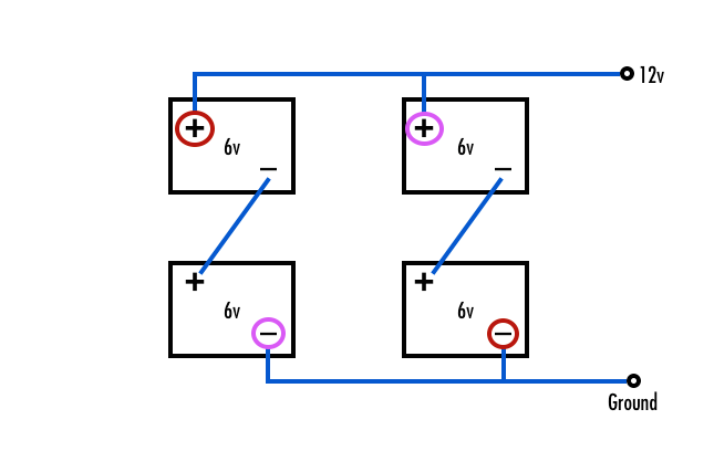
We can get as much as 170 amp-hours per day in summer, although more typically it is about 120 amp-hours.  There have been summer days/nights when we watched our 26″ TV for 15 hours (the Olympics), and there have been days/nights when we ran two laptops for 10 hours and then watched a movie (such couch potatoes!!).

In the dead of winter, around the winter Solstice (December 21), this system can produce about 80-100 amp-hours per day.  The only limitation in winter is when storms cloud the skies for three or more consecutive days.  Three cloudy winter days in a row where we get just 40-60 amp-hours makes us start thinking about supplemental charging or cutting back on our power use.

Our weird choices for solar panel sizes were due to what we already owned from our first solar panel installation (a 130 watt panel) and what was available in the store at the time of purchase (120 watt panels).  If we were buying today, we would have purchased four 150 watt panels as shown above.

This system will allow you to run everything inside your rig but the air conditioner and big power tools.  We have even used it to run a small compressor to change a flat tire on the rig (on four different occasions, ugh!).


RV Full-timer’s System Installation

Installation follows the same guidelines as the smaller systems described in our Solar Power Tutorial Part II, but is just a little more complicated.  An outline of the installation follows.

(1) Install the solar panels on the roof

We wired ours in series, but wiring in parallel may be preferable.  A discussion about the pros and cons of wiring the panels in parallel versus series comes on the next page of this tutorial along with a discussion of wire gauge sizes.  Run the wires down through the refrigerator vent to the battery compartment. If the fridge is in a slide-out, run the wires down the outside of the gray or black water vent pipe

(2) Install the batteries in the battery compartment

Not many RV’s have enough battery boxes for four 6-volt batteries, especially trailers.  Often the battery boxes are too short as well, since 6-volt batteries have the same footprint but are taller than the typical 12-volt Group 24 batteries that are shipped with RVs from the factory.  Here are example 6 volt battery boxes and Group 24 12 volt battery boxes.

If you haven’t purchased your RV yet, you may be able to get the manufacturer or dealer to modify the battery boxes for you as part of the deal (that’s what we did with NuWa on our fifth wheel).  Wire two pairs of the batteries in series to form two 12-volt batteries, and wire those two pairs in parallel.

RV Solar Panel Installation Outback Charge Controller

Outback 60 amp charge controller

(3) Install the solar charge controller near the battery compartment

Connect the wires that come from the solar panels to one side of the charge controller and wire the batteries to the other side.  It is best to crimp eyes on the ends of the cables.

(4) Install the inverter near the battery compartment

Wiring the inverter to the AC wiring system in the RV is complex.  The proper way to wire it is to place the inverter as close to the batteries as possible. Protect the DC side with a big fuse, and wire it to a transfer switch. We are not master electricians, and we took a short cut on our system that not everyone would be comfortable with but that works very well for us.

We positioned the inverter next to the DC to AC converter in the basement of the fifth wheel and wired it directly to the batteries.  The converter is located next to an AC outlet that it uses for power to run (the converter uses the AC power to charge the batteries). 

When we use shore power, we plug the converter into the AC outlet to allow the converter to do its normal job of charging the batteries.  However, we use shore power only a few nights a year, at most.

When we dry camp, which we do virtually 100% of the time, we unplug the converter from the AC outlet so it is totally dormant and not in use, and then we plug the inverter into the AC outlet instead.

The inverter and converter are never “on” at the same time.

The inverter draws its power from the batteries and converts that DC power into AC power. That is, it generates AC power which it supplies to the rig backwards through the AC outlet it is plugged into.

This is very non-standard and would be frowned upon by master electricians.  What would concern them is that when the rig is in this configuration, the shore power outlet on the outside of the trailer is live, with power coming out. Accidentally plugging the shore power cable into the shore power outlet on the outside of the RV while the inverter is turned on would be disastrous. However, because we almost never use our shore power cable and we rarely change our setup to switch between dry camping and hooking up (since we dry camp almost exclusively), this method has worked fine for us for over seven years.

This is not a recommended strategy if you plan to switch between dry camping and using electrical hookups frequently.

We also connect the two 50 amp AC legs of our 50 amp coach by plugging a modified extension cord with a male connector on each end into one outlet on each leg. We have two outlets next to each other in the bedroom, one on each of the 50 amp legs in the trailer, that are ideal for this purpose. We plug the “cheater” cord into each outlet, effectively connecting the two 50 amp halves of the RV together at that point.

It is handy to wire the inverter to a simple toggle switch located somewhere inside the RV so you can turn the inverter on and off from inside the rig without having to go outside to the battery compartment each time you want to turn on your AC power.

Liveaboard Cruiser’s Solar Power System – 24 Volt Solar Panels

Marine sailboat solar panel installation

A large arch installed off the back end makes it possible to use very big panels. Note the shade on the panels from the mast and shrouds. The panels are producing about 50% of their potential power right now!

A system like the above would work fine on a sailboat.  However, another style of design — which we ended up using — is the following.  Of course, this system could be used on an RV as well.

3 250 watt (24-volt) solar panels ($1200)
1 Outback FlexMax 80 MPPT charge controller ($650)
10 gauge wire rated for outdoor use ($200)
4 AGM 4D 12 volt batteries ($2,000)
1 Combiner Box & breakers ($180)
Go Power 3000 watt pure sine wave inverter ($550)

Total parts cost:  ~$4,800

Solar Panel Arch:  ~$2,000-$8,000

Wild guess at an installer’s fee:  ~$1,500-2,500

This system is rated to produce 750 watts at 24 volts and has a 650 amp-hour battery bank.

System Comparison – How do these two full-timer/liveaboard systems differ?”

The system we installed on our sailboat was bigger and more robust than the one we installed on our trailer. If we were to install a solar power system on our RV today, it would be what we put on our boat. Here are the differences between the two:

AGM versus Wet Cell Batteries

One basic difference between the sailboat design and the RV design is the use of AGM batteries rather than wet cell batteries. AGM batteries are not only maintenance free but they can be operated while lying on their sides, whereas wet cells prefer to be upright. They also charge up faster and discharge more slowly.

There is less need for expensive AGM batteries in an RV than on a sailboat since an RV never lies on its side the way a sailboat does while sailing. However, that said, gazillions of cruising boats have sailed around the world with wet cell batteries, through all kinds of storms and mayhem, with no problem, so AGM batteries are by no means required on sailboats. On the other hand, if you have the money and don’t want to be hassled with battery maintenance on your RV, go for AGM instead of wet cell!

 To learn more about AGM versus Wet Cell Batteries, see this article:

Wet Cell vs. AGM Batteries ~plus~ Wiring Tips

Physical Panel Size

The primary difference between the two systems is the size of the solar panels.  An RV has things sticking out of the roof that may hamper the installation of very big solar panels (hatches, fridge vents, air conditioning units, TV antenna, domes, etc.).  So the slightly smaller 150 watt panels may be easier to position on the roof than the big 250 watt panels. Going even smaller (120 watt or 100 watt) may be advantageous.

Finding a place for solar panels on a sailboat is challenging, but the best solution is often to build an arch over the back of the boat, as far behind the end of the boom as possible.  This arch can be designed to support large panels.  See our Sailboat Solar page for more details about our arch and panel installation.  If you are a west coast sailor, consider going to Baja Naval in Ensenada, Mexico, and having Alejandro Ulloa install your arch.  His stainless steel fabrication is by far the highest quality and most beautiful we have seen in all of the US West Coast and Mexico.

24-volt versus 12-volt

This sailboat system differs slightly from the first RV system shown above in that rather than being a strictly 12-volt system, one part of the circuitry is 24-volt (the portion between the panels and the charge controller), and one part of the circuitry is 12-volt (the portion between the charge controller and the batteries). 

Marine sailboat RV Solar Panel installation combiner box

The combiner box contains a breaker for each panel and combines the 3 wires from the panels into 1 for the charge controller.

The charge controller steps down the voltage from 24-volt to 12-volt (and correspondingly doubles the current).  Large panels aren’t available in 12-volt configurations.  Also, the wiring for 24-volt panels can be slightly thinner gauge, which is advantageous (discussed in more detail on the next page of this tutorial).

Combiner Box and breakers

The other difference is that this system uses a combiner box and circuit breakers.  This makes for a more professional installation and can be used on any/all solar power installations that use more than one panel in parallel.  The combiner box sits between the panels and the charge controller.  One of its purposes is to combine the three wires coming from the three panels into one wire that goes to the charge controller.  The other purpose is to provide a breaker for each solar panel so that if something goes wrong the panel can be shut down easily or will trip the breaker automatically.

Liveaboard Cruiser’s System Installation

Installation of a solar power system on a sailboat is more complicated that on an RV simply because the panels are flying out there on some crazy scaffolding in the sky and the batteries are scattered about the bilge of the boat somewhere. The solar panels and batteries are often separated from each other by a big distance.  Finding space for batteries, installing them so they will stay in place even if the boat flips upside down, and snaking wires down the inside of stainless steel tubing in an arch is not all that easy.

The things to keep in mind are simply:

– Install the panels so they get shaded as little as possible by the mast and boom
– Make the wire runs as short and direct as possible
– Install the charge controller as close to the batteries as possible

Our Experience on Our Sailboat

The system outlined here is basically the system we have on our sailboat, except we have three 185 watt panels instead of three 250 watt panels (we weren’t sure if the bigger panels would be physically too big.  In hindsight they would have probably fit fine).

We have anchored out over 750 nights, usually for months at a time.  In a typical day we use two laptop computers for about 4-8 hours and watch a movie on our 22″ TV/DVD (with power hogging sub-woofer & surround-sound) at night.

We get about 220 amp-hours (at 12 volts) per day in the summertime and about 165 amp-hours per day in the wintertime, provided the panels are unshaded all day.  We have found that the winter prevailing winds on the Pacific Mexican coast usually position the boat so the mast shades the panels for a few hours each afternoon, dropping our typical daily total to 150 amp-hours.

We have found that if we run both our DC refrigerator and our separate DC freezer (both of which both cycle on and off 24/7 — a very different load than a few hours of continuous computer or TV use — we come up a little short charging the batteries each day in winter. 

However, if we turn off the freezer (which uses about 50-70 amp-hours every 24 hours all by itself!), our batteries are fully charged and in “float” mode by mid-afternoon each day throughout the winter.  So — provided we can live without frozen meat and ice cubes (gasp!) — we can sit at anchor indefinitely without ever going into a marina or running the engine for supplemental charging from the alternator.  This is a good thing, because our fancy Balmar smart charger/alternator combo gave up the ghost in Huatulco, and we waited eight weeks at anchor for a replacement to come down with a friend from the US.  We don’t have any kind of generator on the boat.

Further Discussion

These two solar power systems have worked well for us in their different settings.  I’ve described them here without any background theory because they will do the job for most full-time RVers and cruisers just as they are.  However, there are lots of things to think about when choosing the different components that make up these two systems.  There is a more detailed discussion of those issues on the next page: 

Solar Tutorial Part IV – Panels & Wiring ->

Most of the components for an RV or marine solar power installation can be purchased at Amazon.

Shown here is a complete full-timer's kit (far left), a big charge controller (middle) and a big inverter (right). More comprehensive listings of each component type can be found at the following links:

Purchases at any of our Amazon links help cover our out-of-pocket costs for operating this site -- thanks!


Subscribe
Never miss a post — it’s free!

FURTHER READING – RELATED ARTICLES

SOLAR POWER OVERVIEW and TUTORIAL

BATTERIES and BATTERY CHARGING SYSTEMS

LIVING ON 12 VOLTS

Our most recent posts:

More of our Latest Posts are in the MENU.   New to this site? Visit RVers Start Here to find where we keep all the good stuff. Also check out our COOL NEW GEAR STORE!! *** CLICK HERE *** to see it!